Introduction
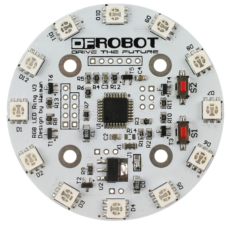
The Rainbow Ring board has been upgraded to version 3! This is probably the most beautiful LED ring ever. Each led on the ring can be controlled seperatly on its brightness and colors (RGB). It comes with pre-burned bootloader which has several built in led scripts.It allows I2C/Serial communication from any MCU and can be serially linked to make a beautiful Art piece via I2C.
Specificiation
- CPU: Atmega 168P (Optiboot Lilypad Board in Arduino IDE)
- Bootloader: Optiboot diecimila
- Supply voltage:5V
- Output voltage:5V
- Interface: Serial/I2C/Digital pins
- Push button x2
- 12 SMD RGB LED
- Firmware upgradable
- Stand-alone operation: No microcontroller needed for light script playback
- Diameter: 61 mm
- Space between two holes: 29 mm
Hardware Requierments
Preparatory Work
- The Rainbow Ring ships with no pin headers. This gives you the option to solder the pins according to your project needs. Before starting to program the LED Ring you should solder the pin headers on to the board.
- CAUTION: Only supply power to 1 of the 3 power pins provided at any one time.
- Download the library Rar file (New RAR file with additional sample code)
- NOTE: This library has yet to be upgraded to be compatible with IDE V1.0 Please use Arduino 0023
- How to change board
-
  -
    step1: Once it's downloaded, unzip the files as normal.You will see the following list.
-
  -
    step2: Open ***boards and programmers-arduino / boards***.
-
  -
    step3: Meanwhile,open Arduino 0023 ***Arduino 0023 / hardware / arduino***.
-
  -
    step4: Put the file ***boards*** of step2 instead of the one ***boards*** of step3. Then re-open Arduino 0023 and select: ***\[Optiboot\] Lilypad Arduino w/Atmega 168***
Method of Use
1.FTDI Connection Instructions
The following picture is the connection diagram.Now,you can use code RGB_Ring_V3 in the zip to test it, directly upload code to Lilypad by FIDI and control it.Take note that the library for RGB_Ring_V3 is a bit different from other Arduino library. There are only an h file and an example pde file under the library folder. Just make sure the RGB_Ring_V3 folder is copied to the libraries folder for your Arduino 0023.
NOTICE: Because of the libary, setting the baud rate is need for double in the serial monitor than in the code.

2.I2C Connection Instructions
NOTICE: Do not connect 5V if already connected from the FTDI board.Connect your Arduino to the Rainbow Ring. Since we are providing power from the FTDI board do not plug in the 5V Vcc to the I2C side of the Rainbow Ring. The only 3 wires you need to connect are the SDA to pin 4, SCL to pin 5, and GND.

The connection is completed. Then, the UNO as the sender, the SenderV3.pde sketch in the folder needs to be uploaded to the UNO, and, the Rainbow Ring as the receiver, the ReceiverV3.pde sketch in the folder needs to be uploaded to the Rainbow Ring. Now, you can use UNO's serial to controll the Rainbow Ring by different commands.
Or, you can consult the code below, which is provided by a client. He changed the command mode by 16 binary. You can also have a try!
UNO as the Sender
//Code for arduino IDE 1.0.5
// for DFROBOT RGB LED RING

#include <Wire.h>


//  Commands must start and end with same number if F1,1,60,0,0,F1 will set led 1 to red
//  The commands sent to the RGB ring via I2C must start and end with the same byte to work.
//  The following commands are available.
//  [RGB values are selectable from 0-63]
//
//  0xF0   Timer2(uint8_t)        1= enable 0= disable       ie F0,01,F0   will enable timers
//  0xF1   set_led_rgb (uint8_t led, uint8_t red, uint8_t green, uint8_t blue);  i.e. F1,01,3f,3f,3f,F1 will set LED1 to white
//  0xF2   set_led_unicolor(uint8_t led, uint8_t rgb, uint8_t var);
//  0xF3   set_all_rgb (uint8_t red, uint8_t green, uint8_t blue) ;
//  0xF4   set_all_unicolor(uint8_t rgb, uint8_t var)
//  0xF5  rotate(uint8_t color,uint8_t dir)  color = 0-7,  dir 0=none, 1=cw, 2=ccw
//          colour determines the component to rotate, i.e.
//                 colour =1 is red and will just rotate the red component.
//                 color 7 is white and will rotate all the LEDs.


//  0xF7  set wobble pattern 3      ?
//  0xFA swaywobble (uint8_t _delay,uint8_t dir)
//  0xFB ?
//  0xF8  serialOn(uint8_t)   1= turn serial on, anything else = serial off.
//        Serial output is at 38400 but causes lots of flickering so better to turn off.

byte buffer[20];
byte i;
byte counter;
byte c;

void setup() {


   Wire.begin(); // join i2c bus (address optional for master)


 Wire.beginTransmission(4);
//Set allRGB to Blue for 1/2 second
  SetAllRGB(0,0,0x3F);
  delay(500);
  //Set allRGB to Red for 1/2 second
  SetAllRGB(0x3F,0,0);
  delay(500);
  //Set allRGB to Green for 1/2 second
  SetAllRGB(0,0x3F,0);
  delay(500);


  buffer[0]=0xF8;  //turn serial off to eliminate flicker
  buffer[1]=0xF8;
  RGBringSend(2);

  delay(250);
  SetAllRGB(0,0,0);   //turn all LED off.

  delay(500);

}


void loop()
{
 delay (1000);

 //turn a red led on and
 for (counter=0; counter <72;counter++){


   SetRGB_led(counter%12,63,63,63);

   SetRGB_led(11+counter%12,63,0,0);

   SetRGB_led(10+counter%12,0,63,0);
   SetRGB_led(9+counter%12,0,0,63);
   SetRGB_led(8+counter%12,0,0,10);
   SetRGB_led(7+counter%12,0,0,0);


   delay(40);
 }
 //slowly turn all LED on and increase brightness
 for (c=0; c <63;c++){
    SetRGB_led(0,c,0,0);
    SetRGB_led(1,0,c,0);
    SetRGB_led(2,0,0,c);
    SetRGB_led(3,c,c,0);
    SetRGB_led(4,c,0,c);
    SetRGB_led(5,0,c,c);
    SetRGB_led(6,c,c,c);
    SetRGB_led(7,0,0,c);
    SetRGB_led(8,0,c,0);
    SetRGB_led(9,c,0,0);
    SetRGB_led(10,c,0,c);
    SetRGB_led(11,c,c,0);
   delay(3);
 }
 //slowly dim LED
  for (c=63; c >0;c--){
    SetRGB_led(0,c,0,0);
    SetRGB_led(1,0,c,0);
    SetRGB_led(2,0,0,c);
    SetRGB_led(3,c,c,0);
    SetRGB_led(4,c,0,c);
    SetRGB_led(5,0,c,c);
    SetRGB_led(6,c,c,c);
    SetRGB_led(7,0,0,c);
    SetRGB_led(8,0,c,0);
    SetRGB_led(9,c,0,0);
    SetRGB_led(10,c,0,c);
    SetRGB_led(11,c,c,0);
   delay(3);
 }
 //turn 4 LED on and then rotate all of them
     SetAllRGB(0,0,0);   //turn all LED off.
     SetRGB_led(0,63,0,0);
     SetRGB_led(3,0,63,0);
     SetRGB_led(6,0,0,63);
     SetRGB_led(9,63,63,0);
     for (c=50 ; c>10 ; c--){
       LEDrotate(7,1);  //clockwise rotate all colours
       delay(c*10);
     }
     for (c=10 ; c<50 ; c++){
       LEDrotate(7,2);  //anticlockwise
       delay(c*10);
     }
}

void SetRGB_led(int led,int rr,int gg,int bb)
{
  buffer[0]=0xF1;
  buffer[1]=led%12;
  buffer[2]=rr;
  buffer[3]=gg;
  buffer[4]=bb;
  buffer[5]=0xF1;
  RGBringSend(6);
}

void SetAllRGB(int rr,int gg, int bb)
{
  buffer[0]=0xF3;
  buffer[1]=rr;
  buffer[2]=gg;
  buffer[3]=bb;
  buffer[4]=0xF3;
  RGBringSend(5);
}
void LEDrotate(int colormask,int dir)
{
  buffer[0]=0xF5;
  buffer[1]=colormask;
  buffer[2]=dir;
  buffer[3]=0xF5;
  RGBringSend(4);
}

void RGBringSend(int commandLength)
{
  Wire.beginTransmission(4);
  for(i=0;i<commandLength;i++){
    Wire.write(buffer[i]);
  }
  Wire.endTransmission();
}
Rainbow Ring as the receiver
#include "RGB_Ring_V3.h"
#include <Wire.h>

//****************************************
//  updated 18/06/2013
//  Sketch for DFrobot DFR0141
//  By default serial is turned on so RGB ring will send serial out  at 38400
//
//  The commands sent to the RGB ring via I2C must start and end with the same byte to work.
//  The following commands are available.
//  [RGB values are selectable from 0-63]
//
//  0xF0   Timer2(uint8_t)        1= enable 0= disable       ie F0,01,F0   will enable timers
//  0xF1   set_led_rgb (uint8_t led, uint8_t red, uint8_t green, uint8_t blue);  i.e. F1,01,3f,3f,3f,F1 will set LED1 to white
//  0xF2   set_led_unicolor(uint8_t led, uint8_t rgb, uint8_t var);
//  0xF3   set_all_rgb (uint8_t red, uint8_t green, uint8_t blue) ;
//  0xF4   set_all_unicolor(uint8_t rgb, uint8_t var)
//  0xF5  rotate(uint8_t color,uint8_t dir)  color = 0-7,  dir 0=none, 1=cw, 2=ccw
//          colour determines the component to rotate, i.e.
//                 colour =1 is red and will just rotate the red component.
//                 color 7 is white and will rotate all the LEDs.


//  0xF7  set wobble pattern 3      ?
//  0xFA swaywobble (uint8_t _delay,uint8_t dir)
//  0xFB ?
//  0xF8  serialOn(uint8_t)   1= turn serial on, anything else = serial off.
//        Serial output is at 38400 but causes lots of flickering so better to turn off.


int S1 = 3;
int S2 = 4;
int val1 = 0;     // variable to store the read value
int val2 = 0;
int turn = 0;

int serialOn = 1;

void setup() {
#ifdef UART
    InitUART();
#else
    Serial.begin(38400);           // start serial for output
#endif
    InitIO();

    Wire.begin(4);                // join i2c bus with address #4
    Wire.onReceive(receiveEvent); // register event

    pinMode(S1, INPUT);
    pinMode(S2, INPUT);
    digitalWrite(S1, HIGH);
    digitalWrite(S2, HIGH);
}

void loop() {
    uint8_t led;
    val1 =digitalRead(S1);
    val2 =digitalRead(S2);
    if(val1==LOW){  //Button S1 pushed
        if (serialOn ==1){
            Serial.println("Button 1 Pushed ");
        }

        uint16_t ctr;
        ALLLEDRED();
        delay(300);
        ALLLEDYELLO();
        delay(300);
        ALLLEDGREEN();
        delay(300);
        ALLLEDTURQUOISE();
        delay(300);
        ALLLEDBLUE();
        delay(300);
        ALLLEDFUCHSIA();
        delay(300);
        ALLLEDWHITE();
        delay(300);
        ALLLEDBLACK();
        delay(300);

        for (ctr = 0; ctr < 3; ctr++)    {
            sequence ();
        }
        ALLLEDBLACK();  // test specific LED
        set_led_rgb(0, 64, 0, 0);
        delay(100);
        set_led_rgb(1, 64, 32, 0);
        delay(100);
        set_led_rgb(2, 64, 64, 0);
        delay(100);
        set_led_rgb(3, 32, 64, 0);
        delay(100);
        set_led_rgb(4, 0, 64, 0);
        delay(100);
        set_led_rgb(5, 0, 64, 32);
        delay(100);
        set_led_rgb(6, 0, 64, 64);
        delay(100);
        set_led_rgb(7, 0, 32, 64);
        delay(100);
        set_led_rgb(8, 0, 0, 64);
        delay(100);
        set_led_rgb(9, 34, 0, 64);
        delay(100);
        set_led_rgb(10, 64, 0, 64);
        delay(100);
        set_led_rgb(11, 64, 0, 32);
        delay(100);
        for (ctr = 0; ctr < 24; ctr++)    {
            rotate(7,CW);
            delay(50);
        }

        ALLLEDBLACK();  //test rotate led
        set_led_rgb(3, 64, 0, 64);
        for (ctr = 0; ctr < 60; ctr++)    {
            rotate(1,CW);
            rotate(3,CCW);
            delay(50);
        }
        ALLLEDBLACK();
        ALLLEDYELLO();
        delay(50);
        for (ctr = 0; ctr < 5; ctr++)    {
            swaywobble(50,CW);
        }
        ALLLEDBLACK();
        setwobble(0xFFFF);

        ALLLEDBLACK();
        for (ctr = 0; ctr < 3; ctr++)    {
            fader();
        }
        ALLLEDBLACK();
        for (ctr = 0; ctr < 3; ctr++)    {
            fader_hue ();
        }
        ALLLEDBLACK();
        for (ctr = 0; ctr < 400; ctr++) {
            color_wave (45);
        }
        for(ctr = 0; ctr < 5; ctr++) {
            disable_timer2_ovf();
            delay(100);
            enable_timer2_ovf();
            delay(100);
        }


    }else if(val2==LOW){
        if (serialOn ==1){
            Serial.println("Button 2 Pushed ");
        }
        switch (turn){
        case 1:
            ALLLEDRED();
            break;
        case 2:
            ALLLEDYELLO();
            break;
        case 3:
            ALLLEDGREEN();
            break;
        case 4:
            ALLLEDTURQUOISE();
            break;
        case 5:
            ALLLEDBLUE();
            break;
        case 6:
            ALLLEDFUCHSIA();
            break;
        case 7:
            ALLLEDWHITE();
            break;
        default:
            ALLLEDBLACK();
            break;
        }
        delay(200);
        turn++;
        if(turn==8) turn=0;

    }else{      // command code
        if(Command[0]>0XEF){
            if(Command[0]<0XFA){
                setwobble(0X0FFF);
                switch (Command[0]){
                case 0xF0:
                    if(Command[1]==1){
                        enable_timer2_ovf();
                    }else{
                        disable_timer2_ovf();
                    }
                    Command[0]=0;
                    break;

                case 0xF1:  // sets the RGB color for 1 specific LED
                    set_led_rgb(Command[1], Command[2], Command[3], Command[4]);
                    Command[0]=0;
                    break;

                case 0xF2:  // set 1 specific color for 1 specific LED
                    set_led_unicolor(Command[1], Command[2], Command[3]);
                    Command[0]=0;
                    break;

                case 0xF3:  // set the RGB value for all LEDs
                    set_all_rgb(Command[1], Command[2], Command[3]);
                    Command[0]=0;
                    break;

                case 0xF4:      // set 1 specific color for 1 specific LED
                    set_all_unicolor(Command[1], Command[2]);
                    Command[0]=0;
                    break;

                case 0xF5:  // set rotate 1 specific color for the LED ring
                    rotate(Command[1], Command[2]);
                    Command[0]=0;
                    break;

                case 0xF6:

                    Command[0]=0;
                    break;

                case 0xF7:  // set array
                    uint8_t w;
                    for(w=0;w<__leds;w++)
                        wobble_pattern_3[w]=(uint16_t)(Command[w*2+1]<<8|Command[w*2+2]);
                    Command[0]=0;
                    break;
                case 0XF8:     //turn serial on or off
                    Command[0]=0;
                    if (Command[1]==1){
                        serialOn =1;
                    }else{
                        serialOn = 0;
                    }
                    break;


                default:
                    Command[0]=0;
                    break;
                }
            }else{
                switch (Command[0]){
                case 0xFA:  //array
                    if(Command[1]>0){
                        swaywobble(Command[1],Command[2]);
                    }else{
                        setwobble(0X0FFF);
                        Command[1]=0;
                        Command[0]=0;
                    }
                    break;

                case 0xFB:  // Flash mob
                    if(Command[1]>0){
                        disable_timer2_ovf();
                        delay(Command[1]);
                        enable_timer2_ovf();
                        delay(Command[1]);
                    }else{
                        enable_timer2_ovf();
                        Command[1]=0;
                        Command[0]=0;
                    }
                    break;

                case 0xFC:  // rotate
                    if(Command[1]>0){
                        rotate(RED, Command[2]);
                        rotate(GREEN, Command[3]);
                        rotate(BLUE, Command[4]);
                        delay(Command[1]);
                    }else{
                        Command[1]=0;
                        Command[0]=0;
                    }
                    break;

                default:
                    Command[1]=0;
                    Command[0]=0;
                    break;
                }
            }
        }
    }
}

void receiveEvent(int howMany)
{
    uint8_t data;
    if (serialOn ==1){
        Serial.println("I received: ");
    }
    ReceivePtr=0;
    while(1 < Wire.available()) // loop through all but the last
    {
        data = Wire.receive();
        if(serialOn ==1){
            Serial.println(data, HEX);
        }
        rx_buf[ReceivePtr]=data; // receive byte as a character
        ReceivePtr++;
        if(ReceivePtr==RX_MASK)  ReceivePtr=0;
    }
    data = Wire.receive();
    if(serialOn ==1){
        Serial.println(data, HEX);
    }
    if(rx_buf[0]==0xF8){
        uint8_t l=rx_buf[1];
        Wire.send(brightness[0][l]);
        Wire.send(brightness[1][l]);
        Wire.send(brightness[2][l]);
    }
    if((ReceivePtr<=COMMAND_SIZE) && (rx_buf[0]==data)) savebuff();

}
PS: Some Details in the Code
1.Some Function Explanation
SET_LED_RGB(LED, RED, GREEN, BLUE) This function sets the RGB color for 1 specific LED. The value for the led should be between 0-11, indicating the 12 leds in the ring (in clock wise, the one on top of DFROBOT logo is LED 0). The red, green, and blue variable is the RGB value for that specific led. These values are intensity for each color from 0 – 64. For example:
set_led_rgb(2, 10, 15, 60);
Will set led 2 on the Rainbow LED Ring to the RGB value R=10 : G=15 : B=60.
SET_LED_UNICOLOR(LED, RGB, VAR) This function changes 1 specific color for 1 specific LED. The rgb value should be 0 – 2, which represent the color RED, GREEN and BLUE. You can also use the "RED", "GREEN", or "BLUE" color enumerator. The var represent the intensity for the specific color. Take note that this function will not affect the intensity of other color on the same LED. For example:
set_led_unicolor(0, RED, 50);
This function change the red color intensity on LED 0 to 50.
SET_ALL_RGB(RED, GREEN, BLUE) This function changes the RGB value for all LEDs. The red, green and blue variable is color intensity for RGB value for all LED.
SET_ALL_UNICOLOR(RGB, VAR) This function changes 1 specific color for all LED. The rgb value should be 0 – 2 represent the color RED, GREEN and BLUE. The var is the intensity for the specific color.
ROTATE(COLOR, DIR) This function will rotate 1 specific color for the LED ring to CW or CCW direction. The color variable is set from 0 – 7 (or you can use color enumerator, RED, GREED, BLUE, YELLOW, TURQUOISE, FUCHSIA, WHITE and BLACK. The dir variable is set from 0 – 2 (or the direction enumerator CW and CCW).
RANDOM_LEDS() This function is to set a random LED(s) and random color on the LED ring. Each time this function is called, some LED will change color or lighten up randomly.
FADER() This function is to perform a fader on all LED on the ring. After this function is called, all the LEDs will fade from zero intensity to full intensity and back to zero intensity (for all color).
FADER_HUE() This function is to perform a color fader on all LED on the ring. After this function is called, the color on all LED will fade from Red to Green, Green to Blue and Blue to Red. The color for all LED remain RED after the function had ended.
2.Rainbow Ring Interaction -- I2C Connection
The following are the commands used to control your Rainbow ring. Included are the parameters needed and the terminal command to execute each command.
NOTE: This sample code has been adapted from earlier Version 2 it has not been fully tested and may have some non-functioning commands, please let us know in the forum if you find problems with this sample code. //Term command`
`#set_led_rgb(LED, INT, INT, INT);  //b     The first parameter is the LED number from 0-11, INT = intensity 0-64`
`#set_led_unicolor(LED, RGB, Int);  //u     RGB = 0, 1, OR 2.`
`#set_all_rgb(R, G, B);         //r     int = intensity  i.e.:RED 00, GREEN 25, BLUE 34: set_all_rgb(00, 25, 34);`
`#set_all_unicolor(RGB, Int);       //a`
`#rotate(color, dir);           //o     Color, direction, color is set from 0-7 and rotation from 0-2`
`#clearCommand();           //- No parameters needed`
`#random_leds ();           //x indicate how many LEDs to light and the delay between each`
`#fader ();             //f how many times to repeat`
`#fader_hue ();             //h how many times to repeat`
`#sequence();               //S how many times to repeat    *NOTE: CAPITAL S`
`#color_wave (0) ;          //w amount to increase ,delay`
Each terminal command should be preceeded by a "c" and ended with an "s". These commands are case sensitve.
This will send the command (c) rotate(o) the color Blue (02) times (99) clockwise (01) send (s)
Please study the sketch, it has been commented to give you a better idea of the functionality.
3.Color Enumeration:
- RED
- GREEN
- Bgdgr
- YELLOW
- TURQUOISE
- FUCHSIA
- WHITE
- BLACK = OFF
rotate CW = 1, CCW= 2
 Get *Rainbow Ring V3 SKU:DFR0141 * from DFRobot Store or DFRobot Distributor.