


TUTORIALS RoboticsArduino Have you ever played with remote control toys? Do you remember how long those toys attracted you? Simple remote control might be unattractive, why not make a smarter robot?Now, let’s try to make a line-follow robot.
1. Line tracking sensor
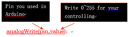
Notice,“analogWrite()” can be only used with the pin which has the PWM function.
Depending on the block diagram upon, we just need to collect the information about the black line and the location of our robot, then do different adjusting.
The robot has 5 infrared geminate transistors for you to detect the line, all the transmitter LED is connected in series, and other 5 receivers are connected with 5 resistors respectively.
Related Category: Robotic > Robot Platform
How to Play With MiniQ 2WD Complete Robot Kit v2.0- Lesson 4(Line Follower)
DFRobot
Mar 21 2017 679
1. Key Points
Have you ever played with remote control toys? Do you remember how long those toys attracted you? Simple remote control might be unattractive, why not make a smarter robot?Now, let’s try to make a line-follow robot.
1. Learn the details about line tracking sensors and motors.
2. Get to know how to follow a line in your code.
3. Finish the task.
4. Materials : Micro USB Cable, MiniQ 2WD Complete robot Kit v2.0, A3 paper (or bigger), black tape
2. Make your robot run
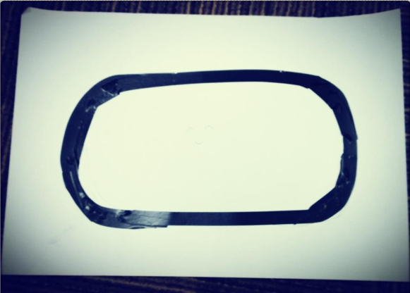
First, you need to make a track for your robot, so you may need black adhesive tape, A3 paper (or bigger). It is easy to make the track: paste your tape on the paper as the route the robot needs to follow. And notice that you’d better use a pencil to draft before pasting, this can make your track nicer. And make the turns as smooth as possible. But if you are a hardcore robot builder, ignore what I said.
1. Track
OK, we have prepared everything, now upload your code, open folder “line_follower” then “line_follower.ino”:
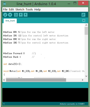
2. Sample code
Put your miniQ on the track, it may not run well, can you help fix this?
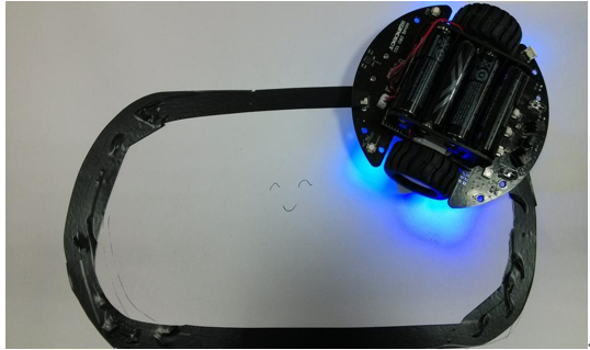
3.: Top View
Function Explained
1. Line tracking sensor
The robot has five line tracking sensors on the bottom side in front. Every sensor is made by an infrared transmitter (infrared LED) and an infrared receiver (infrared photosensitive resistor), since the infrared light can be reflected more from white surface then black, and the resistor value will change with different amount of the light reflected, so we can easily know the location of our robot thus to make it follow the line and never (may be usually if you don’t code well) leave away.
2. Motor Control
Motors can be divided into many kinds depend on different references. We just use a kind of gear motor. It is easy to control, you give it voltage difference in difference direction, it will run in difference direction.
3. PWM
PWM, Pulse Width Modulation, is a kind of technology which uses the digital output of micro controller to control the analog circuit, in your robot, we control the duty cycle to change the speed. In short, it just turn on and turn off the power of the motor, just change the time of turning on and turning off, the motor will performance different speed, as the time of turning is short enough, what we can see is only the motor runs. For example, if duty cycle is 100%, it runs fastest, and if the duty cycle is 50%, the speed will be less, and if duty cycle is 0%, the motor stopped.
Let’s learn something about PWM from these images:
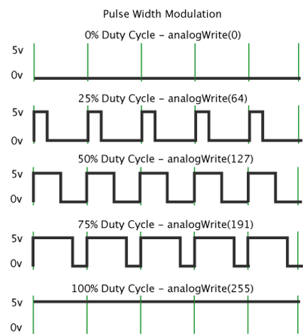
4: PWM hinting
The space between green verticals is a cycle of square wave. The “value” in function “analogWrite(value)” means duty cycle and it ranges from 0(duty cycle:0%)~255(duty cycle: 100%). You can easily know that when “value” is 64, the duty cycle is 25%. And notice you need a high duty cycle to start your motors because of the static friction force. PWM can be also used in LED controlling and some other things.
Notice,“analogWrite()” can be only used with the pin which has the PWM function.
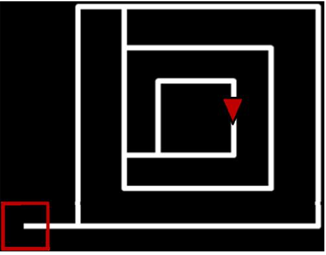
How your program runs:
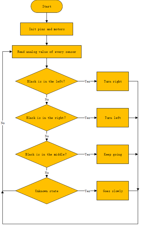
5.Flow chart
Depending on the block diagram upon, we just need to collect the information about the black line and the location of our robot, then do different adjusting.
This is a very simple way to control a robot, in fact, an excellent motor control needs much more knowledge like PID control and fuzzy algorithm. If you want to learn more, just try!
Tips:
1.The corner of the track should be smooth, thus you can make your robot run well.
2. The color of the paper and track is not specific, you can change it, but be robote whether your robot can distinguish the paper and the track.
3. You can also use the field you made for some other idea like put the robot in the middle of the paper and never let it run outside and so on.
Analysis on the Code
Define the pin number
#define EN1 5//pin for run the left motor
#define IN1 12//pin for control left motor direction
#define EN2 6//pin for run the right motor
#define IN2 7//pin for control right motor direction
Read each analog pin
for(i=0;i<5;i++)
{
data[i]=analogRead(i);//store every value in the array
}
Motor control function
void Motor(int M1_DIR,int M1_EN,int M2_DIR,int M2_EN)
Turn right function
Motor(Forward,0,Forward,110);//turn right
Circuit Design
The robot has 5 infrared geminate transistors for you to detect the line, all the transmitter LED is connected in series, and other 5 receivers are connected with 5 resistors respectively.
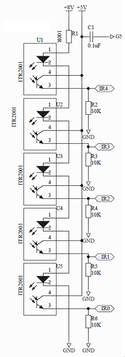
6.Circuit of Line Tracking Sensor
Every geminate transistors use pin1 and pin2 for transmitting, pin3 and pin4 for receiving. Now try to use only 2 geminate transistors for line tracking, that can be more fun.
Related Category: Robotic > Robot Platform
Last Arduino MiniQ 2WD Tutorial: MiniQ 2WD Complete Robot Kit v2.0- Lesson 3(The Light Hunter)
Next Arduino MiniQ 2WD Tutorial: MiniQ 2WD Complete Robot Kit v2.0- Lesson 5(Make It Glow)
Next Arduino MiniQ 2WD Tutorial: MiniQ 2WD Complete Robot Kit v2.0- Lesson 5(Make It Glow)
Robotics ProjectsRobotics ForumRobotics TutorialsRobotics ProductsView Arduino ProductsMore Arduino Related ProjectsArduino Tutorials
REVIEW
Related Product


Recent Blogs

Essential Compatibility Insights for Raspberry Pi 5: What You Need to Know Before Purchase
Discover how to fully harness the Raspberry Pi 5's capabilities, ensuring a smooth upgrade and maximizing your tech projects’ potential.
SELECTION GUIDE Raspberry Pi Apr 19 2024

How to Select SBC (Lattepanda/Raspberry Pi) for Local LLM (LLaMA, LLaMA2, Phi-2, Mixtral-MOE, etc.)
Discover why Lattepanda Sigma is well-suited for local large language model (LLM) operations. Explore its memory and storage capacities compared to other SBCs.
SELECTION GUIDE AI Mar 29 2024

Selection Guide of Linux Systems Compatible with RISC-V Architecture
This article will provide a detailed introduction to several versions of Linux systems, including Ubuntu, Debian, Fedora, OpenSuse, FreeBSD, and OpenBSD, and the compatibility with the RISC-V architecture.
SELECTION GUIDE Mar 27 2024

 Home
Home
 Category
 Shopping Cart
 Me
Me