DISCONTINUED
REPLACED BY: IO Expansion Shield For Arduino(V5) (SKU: DFR0088)
Introduction

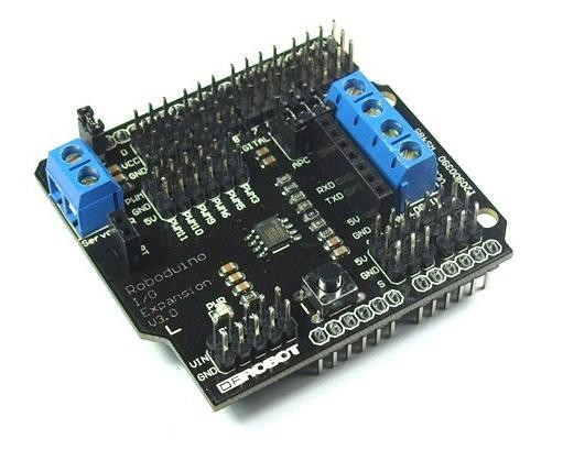
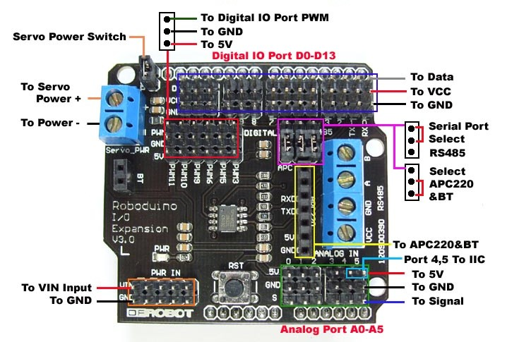
The Arduino I/O Expansion Shield provides an easy way to connect sensors, servos and RS485 device to Arduino board. It expands Arduino’s Digital I/O and Analog Input Pins with Power and GND. It also provides separate PWM Pins which are compatible with standard servo connector. Another unique feature is that the I/O shield has a build-in RS485 converter which allows Arduino communicating with RS485 devices. The communication socket provides an extremely easy way to plug a wireless module such as APC220 Radio Data Module(SKU:TEL0005) and DF-BluetoothV3 Bluetooth module (SKU:TEL0026). It has an individual power input for Servos. A servo power jumper allows user to select using external power or internal power to drive the Servos.
It was replaced by IO Expansion Shield For Arduino(V5) (SKU: DFR0088)
Board Diagram

RS485
It uses an SP485CN chip to handle comms.
The screw terminals (assuming that the three jumpers are set to '485') marked 'A' and 'B' go directly to the IC 'A' and 'B' pins (6 & 7 respectively).
The screw terminal marked VCC goes to the IC VCC pin (8), and also to the board's +5V line (i.e. the Arduino's +5V rail).
The screw terminal marked GND goes to the IC GND pin (5), and also to the board's GND line (i.e. the Arduino's 0V rail).
The chip's DI (Data Input?) pin (4) is connected to the Arduino's Digital Pin 1 (TX).
The chip's RO (Data Output?) pin (1) is connected to the Arduino's Digital Pin 0 (RX), with a resistor pull-up to the +5V rail.
Arduino Digital Pin 2 = Rx/Tx 'Enable'; High to Transmit, Low to Receive
Pin out:
Arduino Digital Pin 0 = RS485 Chip Data Output (Rx) with pull-up to 5V
Arduino Digital Pin 1 = RS485 Chip Data Input (Tx)
Arduino Digital Pin 2 = Rx/Tx 'Enable'; High to Transmit, Low to Receive
Sample Code
RS485 Transmit Data
int EN = 2; //RS485 has a enable/disable pin to transmit or receive data. Arduino Digital Pin 2 = Rx/Tx 'Enable'; High to Transmit, Low to Receive

void setup()
{
  pinMode(EN, OUTPUT);
  Serial.begin(19200);
}

void loop()
{
// send data
  digitalWrite(EN, HIGH);//Enable data transmit
  Serial.print('A');
  delay(1000);
}
RS485 Receiving Data
int ledPin = 13;
int EN = 2;
int val;

void setup()
{
  pinMode(ledPin, OUTPUT);
  pinMode(EN, OUTPUT);
  Serial.begin(19200);
}

void loop()
{
  // receive data
 digitalWrite(EN, LOW);//Enable Receiving Data
 val = Serial.read();
  if (-1 != val) {
    if ('A' == val) {
      digitalWrite(ledPin, HIGH);
      delay(500);
      digitalWrite(ledPin, LOW);
      delay(500);
    }
 }
}
Compatibility
- Arduino UNO
- Arduino Duemilanov
- Arduino Mega 1280/2560
More Documents
- Arduino IO Expansion V4 Schematics
category: Product Manual category: DFR Series category: Shields category: Source category: Discontinued