Introduction
Digital 16A Relay Module is an electrically operated switch, which has a control system (also known as the input circuit) and the controlled system (also known as the output circuit), usually used in automatic control circuit.It is actually "automatic switch" ,using a small electric current to control a larger current.Therefore, the relay has the effects on the automatical automatic adjustment, security, conversion circuit in the circuit and so on .
Relays are used where it is necessary to control a circuit by a low-power signal (with complete electrical isolation between control and controlled circuits), or where several circuits must be controlled by one signal.
The 16A relay module can be used in interactive projects. It can also be used to control the lighting, electrical and other equipments. It can be controlled through the digital IO port, such as solenoid valves, lamps, motors and other high current or high voltage devices.
The main difference between 16A Relay module and the old version relay module is the Max switching current.The max switching current of old version is 10A,and now the new version is 16A.
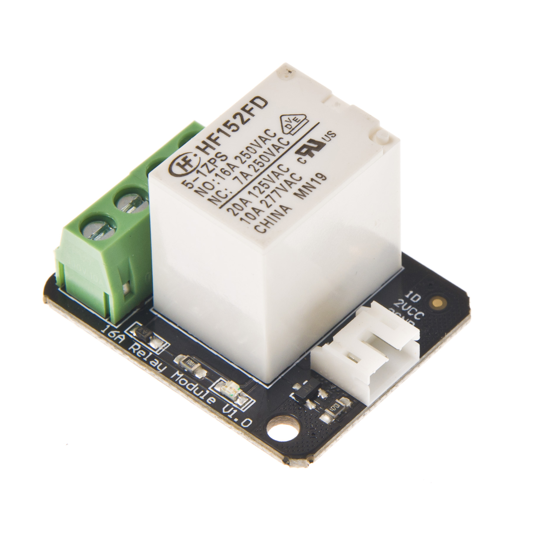
Specification
- Contact Rating (Res. Load):16A 277VAC/24VDC
- Maximum switching voltage: 400VAC(NO)
- Max. switching current: 16A
- Max. switching power: 4700VA
- Operate time (at nomi. Vot.): 10ms max
- Release time (at nomi. Vot.): 5ms max
- Type: Digital
- Single relay board
- Digital Interface
- Control signal: TTL level
Relay Module Pinout
There are a total of 7 pins on the relay module board.
Link Arduino Side:
- Signal
- Vcc
- GND
Link Appliance Side:
- COM(IN): input positive wire from appliance
- N/A(NC): not connected
- NC(OUT1): Normally closed, which means that when the relay is off (a digital low "0" is received from Arduino) the device is ON
- NO(OUT2): Normally open, which means that when the relay is on (a digital high "1" is received from Arduino) the device is ON.

WARNING: Please be very carful not to play with live circuits! 120V or 220V should not be taken lightly. Make sure the appliance to be tinkered with is unplugged from mains. (DO NOT CONNECT IT TO THE WALL WHILE MESSING WITH THE CABLE!)
Test Connection Diagram

Sample Code
/*
 # Product: 16A Relay Module
 # SKU    : DFR0251
 # Description:
 #    This sample code is combined  with the figure above to test the relay module whether works normally.
 # Link:
 #    D     --  2       // Signal
 #    GND   --  GND
 #    VCC   --  VCC
 #    COM   --  13      // INPUT
 #    NO    --  LED     // OUTPUT
 #    LED - --  GND
*/


int Relay = 3;

void setup()
{
  pinMode(13, OUTPUT);         //Set Pin13 as output
  digitalWrite(13, HIGH);     //Set Pin13 High
  pinMode(Relay, OUTPUT);     //Set Pin3 as output
}
void loop()
{
          digitalWrite(Relay, HIGH);   //Turn off relay
          delay(2000);
          digitalWrite(Relay, LOW);    //Turn on relay
          delay(2000);
}
Plugging in an appliance
We will use "out1" for our example, using "out2" will simply reverse the logic, as explained above.
We recommend using a swappable cable to do this with, as using a relay requires you to perform some minor surgery on the appliance's cable.
To plug in an appliance such as a lamp:
Cut and strip a portion of the positive wire so that you end up with two ends of the wire as shown in Figure 2.
The relay should have the positive wire of the device being used connected to "IN" and to "Out 1" as shown in figure 2, and any digital signal pin on the arduino end (For example pin 13).
Sending a digital high or a "1" will trigger the relay. Sending a digital low or "0" will disable the relay.

More Documents
 Get 16A Relay Module (Arduino Compatible) from DFRobot Store or DFRobot Distributor.
Category: DFRobot > Sensors & Modules > Motors & Actuators & Drivers > Relays
category: Product Manual category: DFR Series category: Modules