Introduction
This Gravity Analog 20A current sensor is based on the Hall current sensing principle. It can be used for AC or DC current measurement, has a wide voltage range, a small footprint, requires no soldering and has a high level of precision.
We have added high-voltage isolation in the circuit design for safety reasons and a non-conductive acrylic plate has been attached to the bottom of the PCB to prevent accidents such as short circuits, electric shocks and any other potential danger.
This component is the newest member of our Gravity series. All Gravity components include a standard 3-pin interface to make it simple to use and easy to connect to all Arduino compatible boards. It is ideal for any automation control applications.
 Note: It doesn't recommend measuring the current over 20A. And please be careful careful careful with the high voltage circuit. It is very dangerous!
Features
- Gravity 3 pin interface
- Analog voltage output
- High voltage isolation
- Measures DC and AC current
Specification
- Supply Voltage: 5.0V
- Current Range: 0 ~ ±20A DC, 0 ~ 17A(RMS) AC
- Measurement Endure: 220V AC, 311V DC
- Relative Error: ±3%
- Dimension: 39 * 22 * 17mm/ 1.53 * 0.87 * 0.67 inches
- Interface: Gravity PH2.0-3P
- Weight: 18g
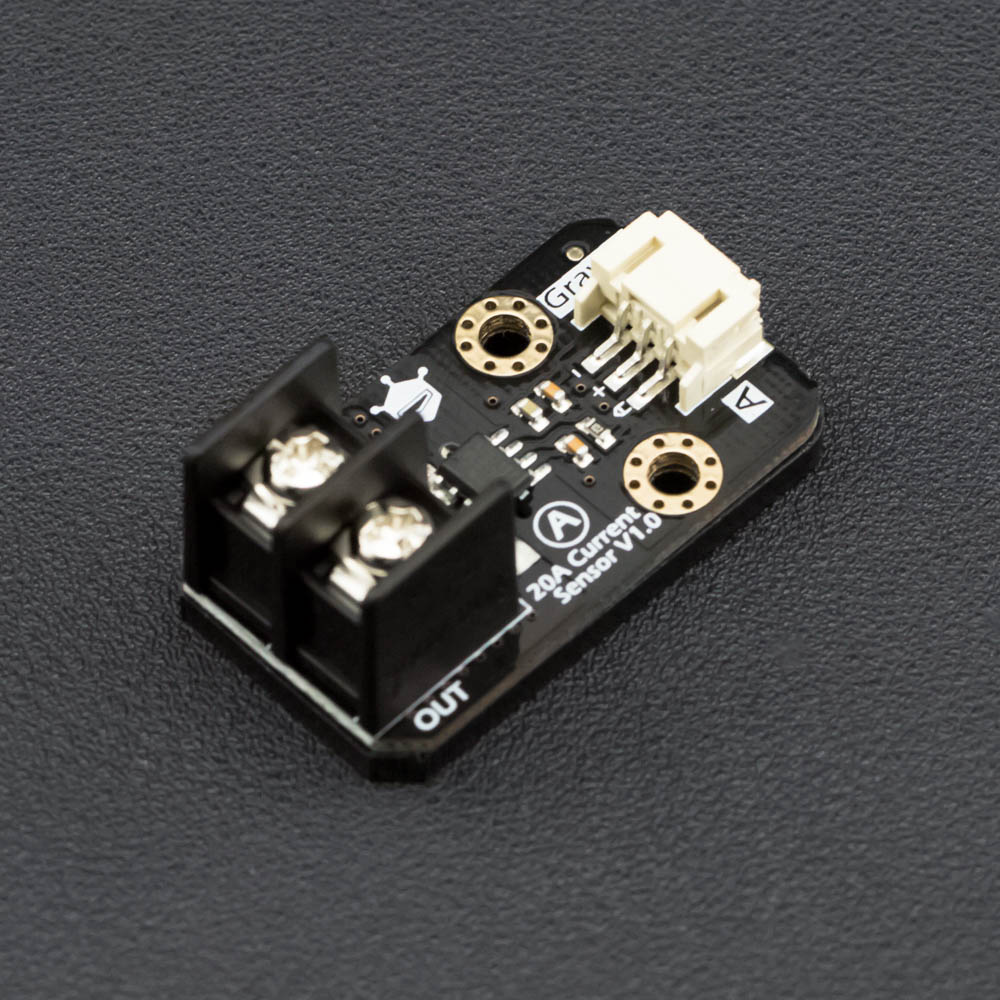
Board Overview

| Num | Label | Description |
|---|---|---|
| 1 | - | GND |
| 2 | + | 5V Input |
| 3 | A | Signal Output |
| 4 | IN | Measuring current Input |
| 5 | OUT | Measuring current Output |
20A Current Sensor
Tutorial
This tutorial demonstrates the usage of the 20A current sensor.
Requirements
- Hardware
- UNO x1
- 20A Current Sensor module x1
- Gravity 3P Analog Wire x1
- Dupont Line Several
- Software
- Arduino IDE Click to Download Arduino IDE from Arduino®
Connection Diagram

Sample Code
/***********************************************************
  This sample code shows how to use 20A current sensor module.

  Created 2016-4-26
  By Bernie Chen <bernie.chen@dfrobot.com>

  GNU Lesser General Public License.
  See <https://www.gnu.org/licenses/> for details.
  All above must be included in any redistribution
 ****************************************************/

/***********Notice and Trouble shooting***************
  1.Connection and Diagram can be found here, https://wiki.dfrobot.com.cn/index.php?title=(SKU:SEN0214)_20A%E7%94%B5%E6%B5%81%E4%BC%A0%E6%84%9F%E5%99%A8#.E6.A0.B7.E4.BE.8B.E4.BB.A3.E7.A0.81
  2.This code is tested on Arduino Uno.
 ****************************************************/

const int currentSensorPin = A0; //define sensor pin
const int mVperAmp = 100; // use 185 for 5A Module, and 66 for 30A Module
float Vref  = 0; //read your Vcc voltage,typical voltage should be 5000mV(5.0V)

void setup()
{
  Serial.begin(115200);
  Vref = readVref(); //read the reference votage(default:VCC)
}

void loop()
{
  /*If you are reading DC current, use this function to read DC current. Then uncomment the AC function.*/
  float CurrentValue =  readDCCurrent(currentSensorPin);
  /*If you are reading AC current, use this function to read AC current,it returns the RMS. Then uncomment the DC function.*/
  //float CurrentValue =  readACCurrent(currentSensorPin);
  Serial.println(CurrentValue);
  delay(500);
}

/*read DC Current Value*/
float readDCCurrent(int Pin)
{
  int analogValueArray[31];
  for (int index = 0; index < 31; index++)
  {
    analogValueArray[index] = analogRead(Pin);
  }
  int i, j, tempValue;
  for (j = 0; j < 31 - 1; j ++)
  {
    for (i = 0; i < 31 - 1 - j; i ++)
    {
      if (analogValueArray[i] > analogValueArray[i + 1])
      {
        tempValue = analogValueArray[i];
        analogValueArray[i] = analogValueArray[i + 1];
        analogValueArray[i + 1] = tempValue;
      }
    }
  }
  float medianValue = analogValueArray[(31 - 1) / 2];
  float DCCurrentValue = (medianValue / 1024.0 * Vref - Vref / 2.0) / mVperAmp;  //Sensitivity:100mV/A, 0A @ Vcc/2
  return DCCurrentValue;
}

/*read AC Current Value and return the RMS*/
float readACCurrent(int Pin)
{
  int analogValue;             //analog value read from the sensor output pin
  int maxValue = 0;            // store max value
  int minValue = 1024;         // store min value
  unsigned long start_time = millis();
  while ((millis() - start_time) < 200) //sample for 0.2s
  {
    analogValue = analogRead(Pin);
    if (analogValue > maxValue)
    {
      maxValue = analogValue;
    }
    if (analogValue < minValue)
    {
      minValue = analogValue;
    }
  }
  float Vpp = (maxValue - minValue) * Vref / 1024.0;
  float Vrms = Vpp / 2.0 * 0.707 / mVperAmp; //Vpp -> Vrms
  return Vrms;
}

/*read reference voltage*/
long readVref()
{
  long result;
#if defined(__AVR_ATmega168__) || defined(__AVR_ATmega328__) || defined (__AVR_ATmega328P__)
  ADMUX = _BV(REFS0) | _BV(MUX3) | _BV(MUX2) | _BV(MUX1);
#elif defined(__AVR_ATmega32U4__) || defined(__AVR_ATmega1280__) || defined(__AVR_ATmega2560__) || defined(__AVR_AT90USB1286__)
  ADMUX = _BV(REFS0) | _BV(MUX4) | _BV(MUX3) | _BV(MUX2) | _BV(MUX1);
  ADCSRB &= ~_BV(MUX5);   // Without this the function always returns -1 on the ATmega2560 https://openenergymonitor.org/emon/node/2253#comment-11432
#elif defined (__AVR_ATtiny24__) || defined(__AVR_ATtiny44__) || defined(__AVR_ATtiny84__)
  ADMUX = _BV(MUX5) | _BV(MUX0);
#elif defined (__AVR_ATtiny25__) || defined(__AVR_ATtiny45__) || defined(__AVR_ATtiny85__)
  ADMUX = _BV(MUX3) | _BV(MUX2);
#endif
#if defined(__AVR__)
  delay(2);                                        // Wait for Vref to settle
  ADCSRA |= _BV(ADSC);                             // Convert
  while (bit_is_set(ADCSRA, ADSC));
  result = ADCL;
  result |= ADCH << 8;
  result = 1126400L / result;  //1100mV*1024 ADC steps https://openenergymonitor.org/emon/node/1186
  return result;
#elif defined(__arm__)
  return (3300);                                  //Arduino Due
#else
  return (3300);                                  //Guess that other un-supported architectures will be running a 3.3V!
#endif
}
Function Introduction: float readDCCurrent(int Pin) , this function is used to measure the DC current. float readACCurrent(int Pin) , this function is used to measure the AC current, and it returns the RMS of AC current. You could only use one of them according to the measured current. Do not use both of them at the same time.
FAQ
For any questions/advice/cool ideas to share, please visit DFRobot Forum
More Documents
 Shopping from Gravity: Analog 20A Current Sensor or DFRobot Distributor.