Introduction
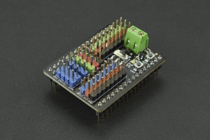
Gravity: I/O Expansion Shield for pyboard is an multifunctional expansion shield specially designed for pyboard v1.1. It is compatible with various sensors and electronic modules of Gravity Series, plug and play, no soldering required. It not only helps you avoid the complex wiring , welding and other operations, but also helps you quickly complete wiring and get started with the sensors or electronic modules, to build prototypes faster.
This expansion shield is equipped with an external power supply port and a 3.3V/VIN power switch, which makes the expansion shield able to drive high current components such as motors and servos. There are 12 sets of digital ports, 8 sets of analog ports, 1 set of serial port and 2 sets of I2C ports on the expansion shield. Various modules can be easily connected to it. Additional, there is an onboard 3.3V LDO, which meets the power demand of multiple modules at the same time. What’s more, the RST button and the USR button are all on the shield, which is easy to reset or restore the motherboard.
 |
1.When put the expansion shield on the pyboard motherboard, please pay attention to the direction. The wire terminal of the expansion shield should be on the same side as the USB port of the pyboard motherboard. 2.Because pyboard motherboard works at 3.3V, limited by the voltage, it does not support 5V analog input. All signal pins are 0 3.If you need to drive high current components such as servos and motors, please connect them to X1 4.The power supply of X1~X4 port can be selected 3.3V or VIN by the power switch. The power supply voltage of the remaining ports are all 3.3V. |
|---|
Specification
- External Power Supply Voltage : 5~12V
- External Power Input Current : <1A
- Connector: Gravity series standard connector
- Ports: 12 sets of digital ports, 8 sets of analog ports, 1 set of serial port, 2 sets of I2C ports
- Interface Signal Level: High Level 3.3V, Low Level 0V
- Analog Input Range: 0~3.3V
- Onboard LDO Output Voltage: 3.3V
- Onboard LDO Output Current: <500mA
- Board Size: 33mm*42.6mm
Board Overview
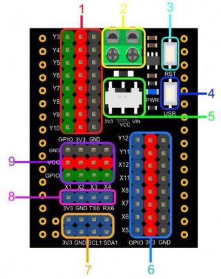
| Num | Label | Description |
|---|---|---|
| 1 | Digital Port | connect to Gravity series digital modules power supply voltage of the port:3.3V Pin:Y3~Y10 |
| 2 | External Power Port | connect to the external power supply input voltage:5~12V |
| 3 | Rest Button | reset the pyboard |
| 4 | User Button | USR button of the pyboard |
| 5 | Power Switch | choose the power supply voltage of X1~X4 ports, 3.3V or VIN |
| 6 | Analog Port | connect to Gravity series analog modules power supply voltage of the port:3.3V Pin:X5~X8、X11、X12、Y11、Y12 |
| 7 | I2C Port | connect to Gravity series I2C modules power supply voltage of the port:3.3V Pin:X9、X10(I2C 1) |
| 8 | UART Port | connect to Gravity series UART modules power supply voltage of the port:3.3V Pin:Y1、Y2(UART 6) |
| 9 | Digital Port (High Current) |
drive high current components such as motors and servos power supply voltage of the port: 3.3V or VIN (can be selected by the power switch) Pin:X1~X4 |
Insertion Direction
When put the expansion shield on the pyboard motherboard, please pay attention to the direction. The wire terminal of the expansion shield should be on the same side as the USB port of the pyboard motherboard.
Tutorial
This tutorial shows how to use this expansion shield in 2 cases. The first case takes the Gravity: Analog Sound Sensor as an example to demonstrate the basic wiring operation, and then reads the analog value through the pyboard to obtain the sound value. In the second case, the 9g Metal Gear Micro Servo is used as an example to demonstrate the usage of the external power supply and the power switch, then the rotation of the servo is controlled by the pyboard. At present, we have written a software library of 10 commonly used sensors or modules, click to open the link.
Requirements
Hardware
- pyboard V1.1 x1
- Gravity: I/O Expansion Shield for Pyboard x1
- Gravity 3pin sensor Cable (or several DuPont Cables) x1
- MicroUSB Cable x1
- Gravity: Analog Sound Sensor x1
- 9g Metal Gear Micro Servo x1
Software
- uPyCraft IDE, Click to download uPyCraft IDE. The uPyCraft IDE is recommended.
- PuTTY, click to download PuTTY
Case 1:Analog Sound Sensor
Connection Diagram
As shown below,connect the sensor to the X5 port of the expansion shield. 
Sample Code
# Analog sound sensor is used to measure the sound.
# Hardware : analog sound sensor, pyboard v1.1
# connect:
#     sensor    pyboard
#     VCC       3V3
#     GND       GND
#     data      X5
from pyb import ADC,Pin
import time
adc=ADC(Pin('X5'))   # Connect sensor to 'X5'
while True:
  val=adc.read()     # Reed the analog value
  print(val)
  time.sleep(0.1)
Expected Result
Copy the sample code in the uPyCraft IDE, save it, then click the DownloadAndRun button, you will see the value of the sound.
As shown in the picture below, when there is sound, the value will increase significantly.

Case 2:Analog Servo(PPM)
Connection Diagram
As shown below,connect the servo to the X1 port of the expansion shield.
| The external power supply must be connected to the USB port of the expansion shield! The power switch must be turned to the VIN side. |
|---|

Sample Code
# Hardware : Servo, PYBoard
# connect:
#     Servo     PYBoard
#     VCC       VCC
#     GND       GND
#     DAT       X1
import pyb
import time
s1=pyb.Servo(1)     # create a servo object on position X1
while(True):
    s1.angle(0)
    time.sleep(1)
    s1.angle(90)
    time.sleep(1)
    s1.angle(0)
    time.sleep(1)
    s1.angle(-90)
    time.sleep(1)
Expected Result
Copy the sample code in the uPyCraft IDE, save it and click the DownloadAndRun button, you will see the servo constantly spinning.
FAQ
| For any questions, advice or cool ideas to share, please visit the DFRobot Forum. |
|---|
More Documents
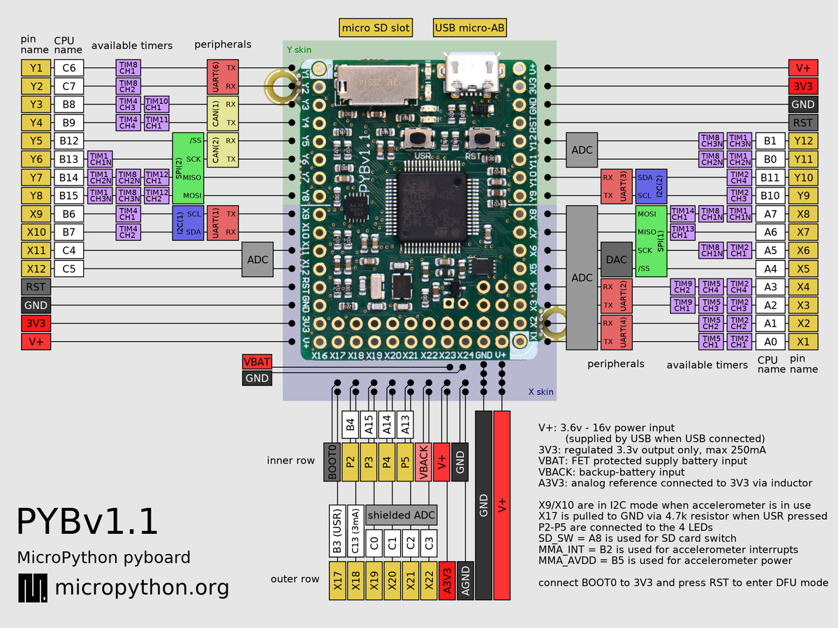
[Schematic] [Layout] Pyboard V1.1 Pinout MicroPython Website MicroPyth Reference Documents Gravity Software Library for Pyboard(github)
 Get Gravity: I/O Expansion Shield for Pyboard from DFRobot Store or DFRobot Distributor.