Introduction
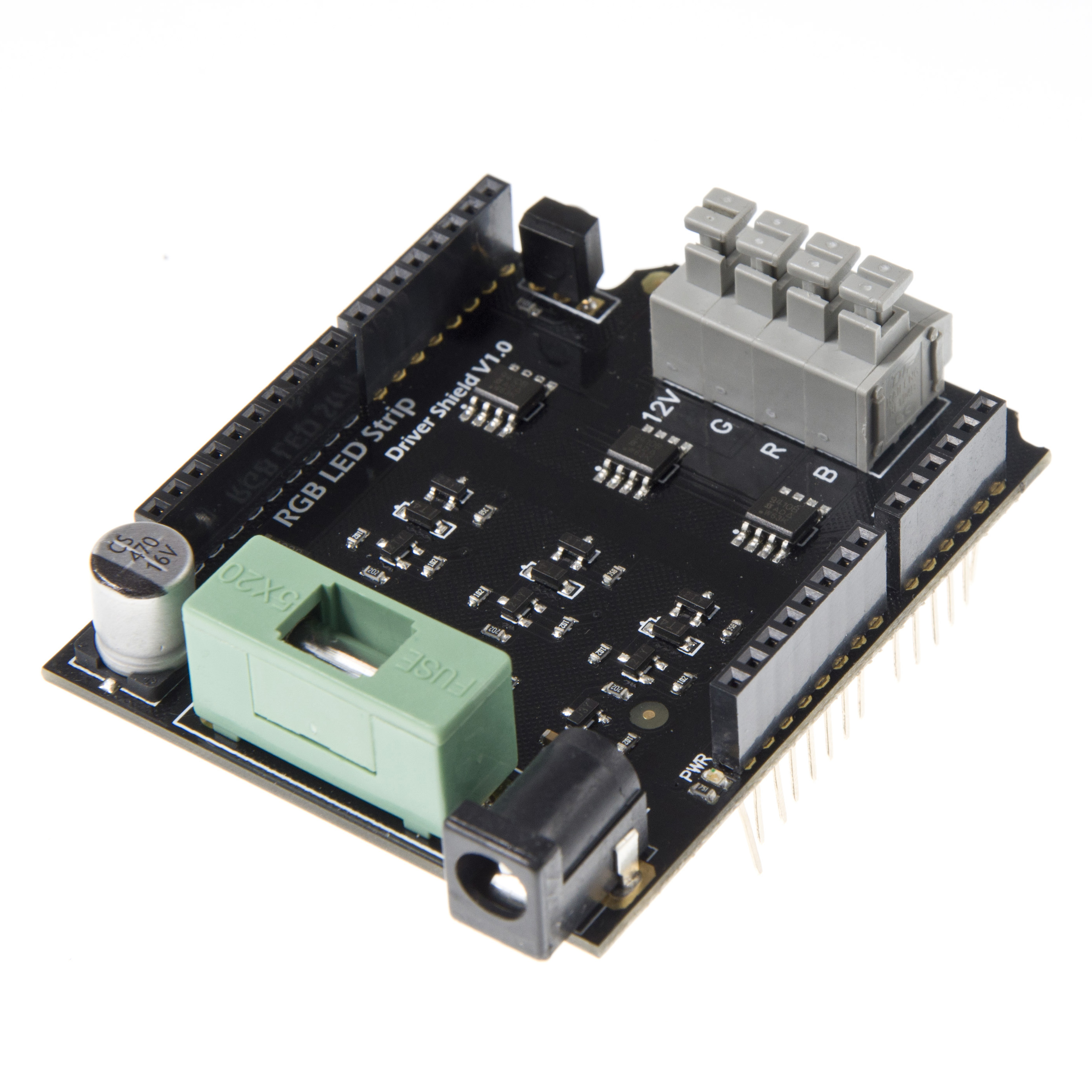
The RGB LED Strip Driver Shield allows an Arduino board to drive the RGB LED Strip. Through control the 3 MOSFEET on the board,you can turn the RGB LED ON/OFF,and show colors differently.
You can also control the RGB LED Strip Driver Shield by the IR remote controller.
The RGB LED Strip Driver Shield connects to an Arduino board using long wire-wrap headers which extend through the shield. This keeps the pin layout intact and allows another shield to be stacked on top.
Arduino uses digital PWM pins 9, 10, 11 to control the MOSFEET on the RGB LED Strip Driver Shield. and the digital pin 4 is used to receive the IR signal.These pins cannot be used for general i/o.
The shield have a fuse,it can limit the current.
Specification
- Supply voltage:<=12V
- Compatible arduino Uno,arduino Mega,Romeo......
- Compatible with 12V RGB LED Strip
- Maximum power is 72W (2A per way)
- Support IR remote control
Pin Out

Arduino Driving Pins:
D9 -> PWM1 (Blue Output control)
D10 -> PWM2 (Red Output control)
D11 -> PWM3 (Green Output control)
IR Recieving Pin:
- D4 -> IR data receiving
PS: This feature could be disable by removing the jumper cap on the shield.
Note:
Commonly we use the common anode RGB LED Strip. So when connecting the RGB Strip to the driver shield, it requires a independent 12v power source for the high power LED strip.
The maximum powering current from this shield is about 9A totally(3A for each way). So it could almost directly drive a 10 meter RGB LED strip.
Sample Code
LED Strip driving code
Here's the basic code for controlling the color of the RGB LED strip.
int RedPin = 10;      //Arduino driving pin for Red
int GreenPin = 11;    //Arduino driving pin for Green
int BluePin = 9;      //Arduino driving pin for Blue

void setColor(int red, int green, int blue)
{
  analogWrite(RedPin, red);
  analogWrite(GreenPin, green);
  analogWrite(BluePin, blue);

}

void setup()
{
  pinMode(RedPin, OUTPUT);    //Init Arduino driving pins
  pinMode(GreenPin, OUTPUT);
  pinMode(BluePin, OUTPUT);
  Serial.begin(9600);
}

void loop()
{
  for (int i=0;i<255;i++)  //Changing Red brightness
  {
    setColor(i, 0, 0);
    delay (10);
  }
  delay(2000);
  for (int i=0;i<255;i++)  //Changing Green brightness
  {
    setColor(0, i, 0);
    delay (10);
  }
  delay(2000);
  for (int i=0;i<255;i++)  //Changing Blue brightness
  {
    setColor(0, 0, i);
    delay (10);
  }
  delay(2000);
  for (int i=0;i<255;i++)
  {
    setColor(i, 0, 255-i);
    delay (10);
  }
  for (int i=0;i<255;i++)
  {
    setColor(255-i, i, 0);
    delay (10);
  }
  for (int i=0;i<255;i++)
  {
    setColor(0, 255-i, i);
    delay (10);
  }
}
IR Receiving Code
For the ir receiving feature, we recommend to use Arduino IRRemote library created by Ken Shirriff. This library is quite easy to use and directly support decoding several different IR protocol.
//Please download the arduino library and install it before compiling the sample code
/*
 * IRremote: IRrecvDemo - demonstrates receiving IR codes with IRrecv
 * An IR detector/demodulator must be connected to the input RECV_PIN.
 * Version 0.1 July, 2009
 * Copyright 2009 Ken Shirriff
 * http://arcfn.com
 */

#include <IRremote.h>

int RECV_PIN = 4; //IR Receiving pin on the driver shield

IRrecv irrecv(RECV_PIN);

decode_results results;

void setup()
{
  Serial.begin(9600);
  irrecv.enableIRIn(); // Start the receiver
}

void loop() {
  if (irrecv.decode(&results)) {
    Serial.println(results.value, HEX);
    irrecv.resume(); // Receive the next value
  }
}
IR Remote control Demo
Use IR transmitter from dfrobot for controlling the RGB led strip.
// 0.1 by pmalmsten http://www.arduino.cc/cgi-bin/yabb2/YaBB.pl?num=1176098434
// 0.2 by farkinga
// 0.3 by farkinga - adds cool behaviors
/* 0.4 by pstrobl
   changed the original program to use on IR Kit For Arduino Model: DFR0107 32 bit controller.
   All keypresses are sent to the serial monitor at 9600 baud.
   pulseIn is always HIGH. The phototransistor in the kit does not invert the signal.
   uses pin 13 for heartbeat debug
   32 bits requires a long variable, so divided up into two 15 bit so can use integer variables
   use the first 15 bits of the 32 bits for remote and data stream verification. This code is always the same for every button press
   use the last 15 of the 32 bits for button press selection. This code changes for each button.
   ignore the middle 2 bits, it never changes.
*/

#define IR_BIT_LENGTH 32    // number of bits sent by IR remote
#define FirstLastBit 15     // divide 32 bits into two 15 bit chunks for integer variables. Ignore center two bits. they are all the same.
#define BIT_1 1500          // Binary 1 threshold (Microseconds)
#define BIT_0 450           // Binary 0 threshold (Microseconds)
#define BIT_START 4000      // Start bit threshold (Microseconds)

#define IR_PIN 4           // IR Sensor pin
#define LED_PIN 13          // LED goes off when signal is received

int debug = 0;              // flag as 1 to output raw IR pulse data stream length in microseconds
int output_verify = 0;      // flag as 1 to print decoded verification integers. same number for all buttons
int output_key = 0;         // flag as 1 to print decoded key integers
int remote_verify = 16128;  // verifies first bits are 11111100000000 different remotes may have different start codes

int Blue_Bright=0;
int Red_Bright=0;
int Green_Bright=0;

int RedPin = 10;
int GreenPin = 11;
int BluePin = 9;

boolean Blue_flag=false;
boolean Red_flag=false;
boolean Green_flag=false;
boolean Flash_flag=false;

void setColor(int red, int green, int blue)
{
  analogWrite(RedPin, red);
  analogWrite(GreenPin, green);
  analogWrite(BluePin, blue);

}

void setup()
{
  pinMode(LED_PIN, OUTPUT); //This shows when ready to recieve
  pinMode(IR_PIN, INPUT);
  digitalWrite(LED_PIN, LOW);

  pinMode(RedPin, OUTPUT);
  pinMode(GreenPin, OUTPUT);
  pinMode(BluePin, OUTPUT);
  Serial.begin(9600);
}

void loop()
{
  digitalWrite(LED_PIN, HIGH);
  int key = get_ir_key();
  digitalWrite(LED_PIN, LOW);  // turn LED off while processing response
  do_response(key);
  if (Flash_flag)
  {
    for (int i=0;i<255;i++)
    {
      setColor(i, 0, 255-i);
      delay (10);
    }
    for (int i=0;i<255;i++)
    {
      setColor(255-i, i, 0);
      delay (10);
    }
    for (int i=0;i<255;i++)
    {
      setColor(0, 255-i, i);
      delay (10);
    }
  }
  else
  {
    if (Blue_flag)analogWrite(BluePin, Blue_Bright);else analogWrite(BluePin, 0);
    if (Red_flag)analogWrite(RedPin, Red_Bright);else analogWrite(RedPin, 0);
    if (Green_flag)analogWrite(GreenPin, Green_Bright);else analogWrite(GreenPin, 0);
  }
  delay(130);                  // 2 cycle delay to cancel duplicate keypresses
}

/*
  wait for a keypress from the IR remote, and return the
  integer mapping of that key (e.g. power button on remote returns
  the integer 1429)
*/

int get_ir_key()
{
  int pulse[IR_BIT_LENGTH];
  int bits[IR_BIT_LENGTH];

  do {} //Wait for a start bit
  while(pulseIn(IR_PIN, HIGH) < BIT_START);

  read_pulse(pulse);
  pulse_to_bits(pulse, bits);
  RemoteVerify(bits);
  return bits_to_int(bits);
}


/*
  use pulseIn to receive IR pulses from the remote.
  Record the length of these pulses (in ms) in an array
*/

void read_pulse(int pulse[])
{
  for (int i = 0; i < IR_BIT_LENGTH; i++)
  {
    pulse[i] = pulseIn(IR_PIN, HIGH);
  }
}

/*
  IR pulses encode binary "0" as a short pulse, and binary "1"
  as a long pulse.  Given an array containing pulse lengths,
  convert this to an array containing binary values
*/

void pulse_to_bits(int pulse[], int bits[])
{
  if (debug) { Serial.println("-----"); }
  for(int i = 0; i < IR_BIT_LENGTH; i++)
  {
    if (debug) { Serial.println(pulse[i]); }
    if(pulse[i] > BIT_1) //is it a 1?
    {
      bits[i] = 1;
    }
    else if(pulse[i] > BIT_0) //is it a 0?
    {
      bits[i] = 0;
    }
    else //data is invalid...
    {
      Serial.println("Error");
    }
  }
}

/*
  check returns proper first 14 check bits
*/

void RemoteVerify(int bits[])
{
  int result = 0;
  int seed = 1;

  //Convert bits to integer
  for(int i = 0 ; i < (FirstLastBit) ; i++)
  {
    if(bits[i] == 1)
    {
    result += seed;
    }

    seed *= 2;
  }
        if (output_verify)
      {
        Serial.print("Remote ");
        Serial.print(result);
        Serial.println(" verification code");
      }
 if (remote_verify != result) {delay (60); get_ir_key();} //verify first group of bits. delay for data stream to end, then try again.
}


/*
  convert an array of binary values to a single base-10 integer
*/

int bits_to_int(int bits[])
{
  int result = 0;
  int seed = 1;

  //Convert bits to integer
  for(int i = (IR_BIT_LENGTH-FirstLastBit) ; i < IR_BIT_LENGTH ; i++)
  {
    if(bits[i] == 1)
    {
    result += seed;
    }
    seed *= 2;
  }
  return result;
}


/*
  respond to specific remote-control keys with different behaviors
*/

void do_response(int key)
{

  if (output_key)
   {
      Serial.print("Key ");
      Serial.println(key);
   }

  switch (key)
  {
    case 32640:  // turns on UUT power
      if (Blue_flag|Red_flag|Green_flag){Blue_flag=false;Red_flag=false;Green_flag=false;Flash_flag=false;}
      else {Blue_flag=true;Red_flag=true;Green_flag==true;}
      Serial.println("POWER");
      break;

    case 32385:  // FUNC/STOP turns off UUT power
      Serial.println("FUNC/STOP");
      break;

    case 32130:  // |<< ReTest failed Test
      Serial.println("|<<");
      break;

    case 32002:  // >|| Test
      Serial.println(">||");
      break;

    case 31875:  // >>| perform selected test number
      Serial.println(">>|");
      break;

    case 32512:  // VOL+ turns on individual test beeper
      Serial.println("VOL+");
      break;

    case 31492:  // VOL- turns off individual test beeper
      Serial.println("VOL-");
      break;

    case 31620:  // v scroll down tests
    if (Blue_flag==true&&Blue_Bright>10)Blue_Bright-=10;
    if (Red_flag==true&&Red_Bright>10)Red_Bright-=10;
    if (Green_flag==true&&Green_Bright>10)Green_Bright-=10;
      Serial.println("v");
      break;

    case 31365:  // ^ scroll up tests
    if (Blue_flag==true&&Blue_Bright<245)Blue_Bright+=10;
    if (Red_flag==true&&Red_Bright<245)Red_Bright+=10;
    if (Green_flag==true&&Green_Bright<245)Green_Bright+=10;
      Serial.println("^");

      break;

    case 30982:  // EQ negative tests internal setup
      Serial.println("EQ");
      break;

    case 30855:  // ST/REPT Positive tests Select Test and Repeat Test
    Serial.println("ST/REPT");
      break;

    case 31110:  // 0
      Serial.println("0");
      break;

    case 30600:  // 1
    Red_flag=true;
    Green_flag=false;
    Blue_flag=false;
    Flash_flag=false;
    Red_Bright=120;
      Serial.println("1");
      break;

    case 30472:  // 2
    Green_flag=true;
    Red_flag=false;
    Blue_flag=false;
    Flash_flag=false;
    Green_Bright=120;
      Serial.println("2");
      break;

    case 30345:  // 3
    Blue_flag=true;
    Green_flag=false;
    Red_flag=false;
    Flash_flag=false;
    Blue_Bright=120;
      Serial.println("3");
      break;

    case 30090:  // 4
    Flash_flag=true;
      Serial.println("4");
      break;

    case 29962:  // 5
      Serial.println("5");
      break;

    case 29835:  // 6
      Serial.println("6");
      break;

    case 29580:  // 7
      Serial.println("7");
      break;

    case 29452:  // 8
      Serial.println("8");
      break;

    case 29325:  // 9
      Serial.println("9");
      break;

    default:
      {
        Serial.print("Key ");
        Serial.print(key);
        Serial.println(" not programmed");
      }
    break;
  }
}
Documents
 Get RGB LED Strip Drivr Shield V1.0 from DFRobot Store or DFRobot Distributor.
Category: DFRobot > arduino > Arduino Shields category: Product Manual category: DFR Series category: Shields category: Source category: Diagram category: DFRobot