[ ]
]
Overview
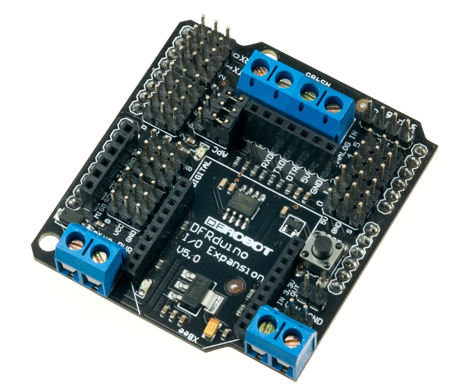
The DFRobot IO expansion board is evolving, this latest V5 IO expansion shield is now supporting Xbee. It combines our popular Xbee shield with IO expansion shield(V4). It even supports SD card which provides the ultimate functional expansion for Arduino so far. As its predecessor, it supports RS485, APC220, Bluetooth communication, servo control.
Update V6:
- V6 uses a colored pin, corresponds to the thread color with digital/analog sensors to prevent reverse polarity or incorrect insertion.
- V6 version fully supports the latest Arduino R3 PIN.
- RS485, removed "enable control" as an automatic half-duplex.
- Add a RS485 bus termination resistor selector switch.
- Add URM04 interface.
- Serial selection jumper pin changed to switch (XBee, RS485, Download mode) to avoid conflict with each other.
Specification
- Support RS485
- Support Xbee (Xbee pro)
- Support Bluetooth
- Support APC220
- Support SD card read/write
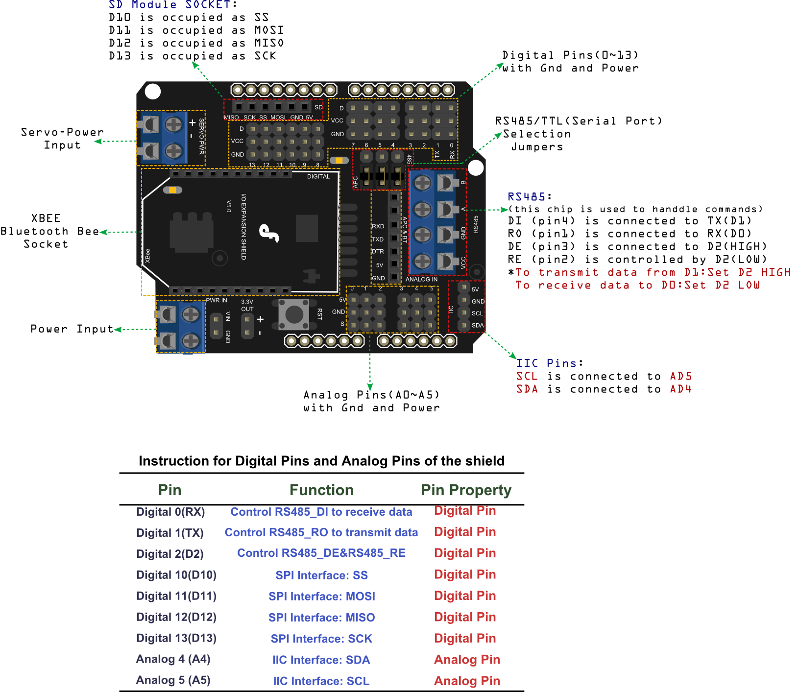
RS485
It uses an SP485CN chip to handle comms.
The screw terminals (assuming that the three jumpers are set to '485') marked 'A' and 'B' go directly to the IC 'A' and 'B' pins (6 & 7 respectively).
The screw terminal marked VCC goes to the IC VCC pin (8), and also to the board's +5V line (i.e. the Arduino's +5V rail).
The screw terminal marked GND goes to the IC GND pin (5), and also to the board's GND line (i.e. the Arduino's 0V rail).
The chip's DI (Data Input?) pin (4) is connected to the Arduino's Digital Pin 1 (TX).
The chip's RO (Data Output?) pin (1) is connected to the Arduino's Digital Pin 0 (RX), with a resistor pull-up to the +5V rail.
The chip's DE (output enable) pin (3) is connected (via a resistor) to the Arduino's Digital Pin 2 - this is active high.
This DE pin is also connected to the chip's RE bar (receiver enable) pin (2) and therefore controlled by the Arduino's Digital pin 2 too - this is active low.
Arduino Digital Pin 2 = Rx/Tx 'Enable'; High to Transmit, Low to Receive
So, to transmit data from Arduino Digital Pin 1 you need to take Digital pin 2 high, and to receive data to Arduino Digital Pin 0 you need to take Arduino Digital pin 2 low.
Pin Out
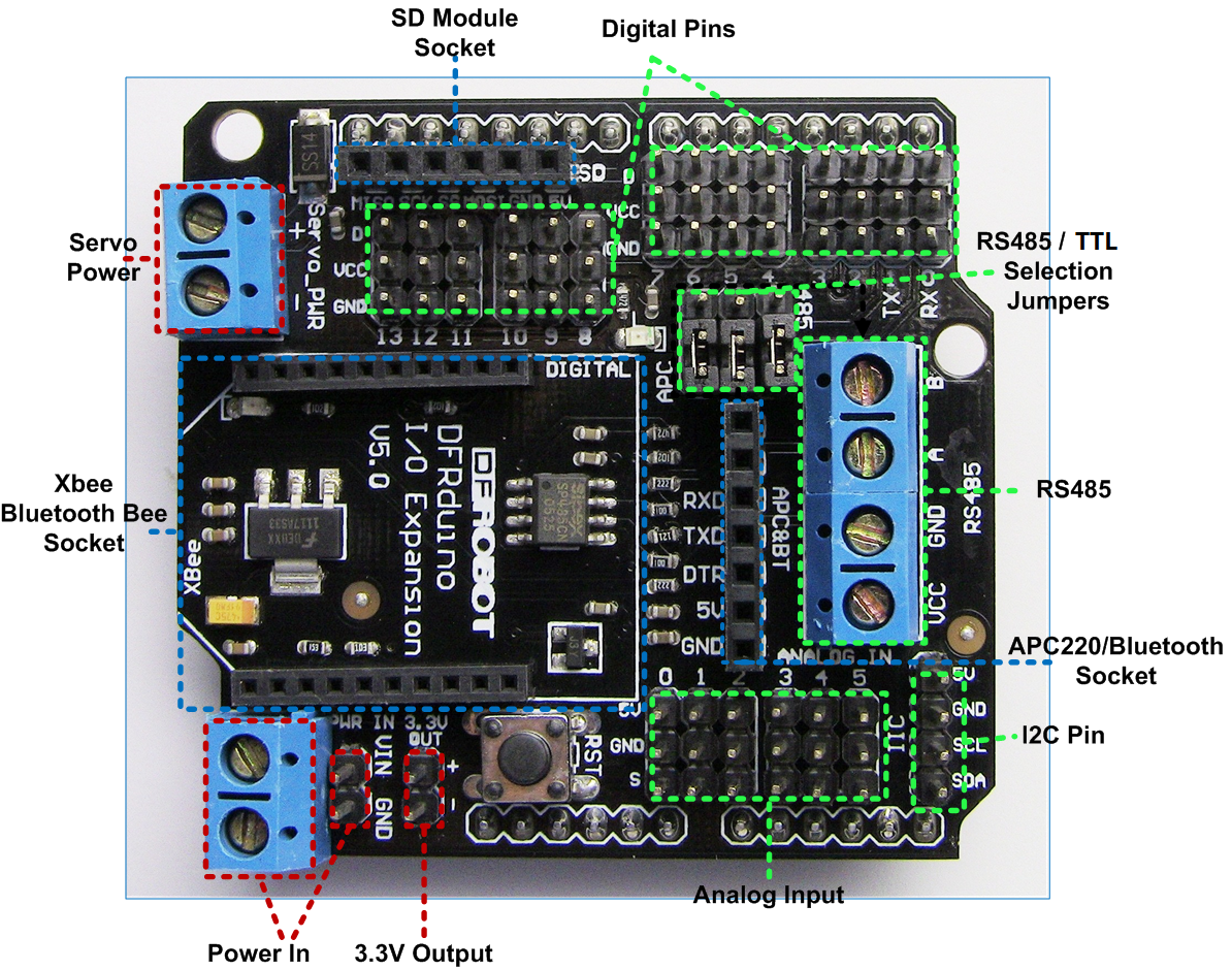
Shield functions & pins usage
Sample Code
RS485 Transmit Data
int EN = 2; //RS485 has a enable/disable pin to transmit or receive data. Arduino Digital Pin 2 = Rx/Tx 'Enable'; High to Transmit, Low to Receive

void setup()
{
  pinMode(EN, OUTPUT);
  Serial.begin(19200);
}

void loop()
{
// send data
  digitalWrite(EN, HIGH);//Enable data transmit
  Serial.print('A');
  delay(1000);
}
RS485 Receiving Data
int ledPin = 13;
int EN = 2;
int val;

void setup()
{
  pinMode(ledPin, OUTPUT);
  pinMode(EN, OUTPUT);
  Serial.begin(19200);
}

void loop()
{
  // receive data
 digitalWrite(EN, LOW);//Enable Receiving Data
 val = Serial.read();
  if (-1 != val) {
    if ('A' == val) {
      digitalWrite(ledPin, HIGH);
      delay(500);
      digitalWrite(ledPin, LOW);
      delay(500);
    }
 }
}
Compatibility
- Arduino UNO
- Arduino Duemilanov
- Arduino Mega 1280/2560
Documents
 Get Gravity: RS485 IO Expansion Shield for Arduino from DFRobot Store or DFRobot Distributor.
category: Product Manual category: DFR Series category: Shields category: source