Introduction
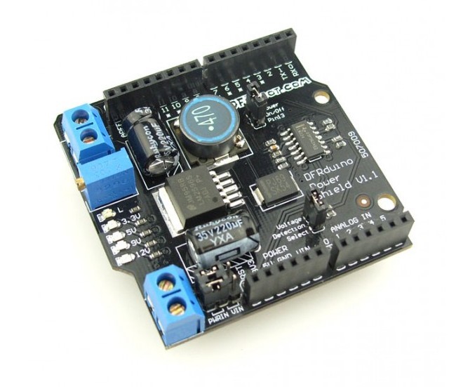
Many Arduino projects may need more than two voltage supplies. When fed with 4.5-35V, this power shield is able to provide a voltage range from 1.25-12V with 3A peak current. Ideal for servo control and other non-standard components. With this shield, your Arduino can now have one power supply for everything.
The power shield has a built-in voltage measuring function which maps the output voltage to Arduino analog pin 0. It can be controlled by Arduino digital Pin 13 to switch on/off.
Specification
- Supply voltage:4.5-35V
- Output voltage:1.25-12V
- Output current: 2A (3A peak)
- Efficiency:90%
PinOut

Tutorial
Usage
There are two methods of operation with this shield, you can:
- Use this shield to regulate external power supply to provide the proper voltage to your Arduino
- Directly level it for servo/modules high power devices
 |
Note for the jumpers near to the Power Input socket: |
| Both jumpers are on left side: This method will only provide regulated power to the PWROUT. i.e. There is no voltage on Vin which is connected with Arduino . | |
| Top jumper is on left side, bottom jumper is on right. This will provide regulated PWROUT, adjusted via the blue potentiometer next to the PWROUT connector. Arduino Vin power will be connected to the external power supply. |
Stack up more power shield to add up different power level outputs. If your Power supply is incompatible with your device and you need to provide power for other devices as well. Adding another power shield will let you regulate a secondary voltage level as well.
Sample Code
This sample code needs an I2C LCD module to display the voltage.
#include <Wire.h>
#include <LiquidCrystal_I2C.h>

LiquidCrystal_I2C lcd(0x27,16,2);  // set the LCD address to 0x27 for a 16 chars and 2 line display

void setup()
{
  lcd.init();
  lcd.backlight();
  lcd.setCursor(0, 0);
  lcd.print("www.DFRobot.com");
  lcd.setCursor(0, 1);
  lcd.print("Voltage: ");
  lcd.setCursor(13, 1);
  lcd.print("V");
}
void loop()
{
      int val;
      float temp;
      val=analogRead(0);
      temp=val/4.092;
      val=(int)temp;//
      lcd.setCursor(9, 1);
      lcd.print(temp);
/*
      lcd.print(0x30+val/100,BYTE);
      lcd.print(0x30+(val%100)/10,BYTE);
      lcd.print('.');
      lcd.print(0x30+val%10,BYTE);
*/
      delay(100);
}| NOTE: If you have a multimeter, you can easily read the output voltage through output terminal without the LCD and LCD displaying code. In other words, voltage regulation is independent. Consider it as a normal shield with function of voltage regulation. |
Result
LCD will display the output voltage from the Power shield.
Trouble shooting
| For any questions and more cool ideas to share, please visit DFRobot Forum |
More
 Get it from Power Shield (Arduino Compatible) or DFRobot Distributor.
category: Product Manual category: DFR Series category: Shields category:source