Introduction
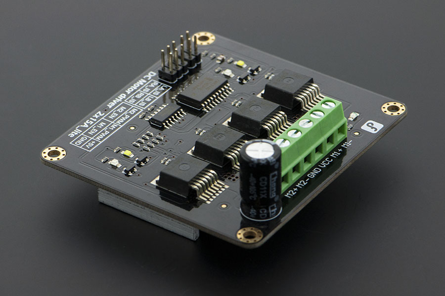
This DC Motor Driver can be used in 4WD mobile robot platforms, combat robots, smart car competition, to drive pumps, electric fans, conveyors, etc. This module uses 4 high-performance & high-current driver chips - BTS7960 with the function of current short, over temperature, over voltage protection. You can control 2 motors with only 4 digital IO at the same time. Dual 15A@13.8V max output current, good responsiveness & braking performance. Four indicator leds are provided for easy and convenient debugging without motors. This DC Motor Driver module is directly compatible with Arduino.
Specification
- Input Voltage: 4.8-27V
- Maximum output current: 15A@13.8V per channel
- Peak output current: 20A@13.8V per channel
- PWM capability: up to 25 kHz
- Interfaces: 4 digital IO (2 PWM output include)
- Driving mode: Dual high-power H-bridge driver
- Other specifications:
- Galvanic isolation to protect the microcontroller
- Dual current detection diagnostic functions
- Short circuit, overheating, over-voltage protection
- Size: 73×68×14mm
- For applications of more than 15A per channel
- Fast switching might damage the board, best to smooth it by software
- Avoid higher rating motors, and use lower PWM whenever possible
Tutorial
Diagram

LA_IS, LB_IS, RA_IS & RB_IS is for current sense and diagnosis.
In normal operation, the IS pin output a low level. In a fault condition, it will output a high level. The following code will show you how to do.
- LA_IS and RA_IS is used for Motor1
- LB_IS and RB_IS is used for Motor2
Sample Code
PWM mode
/*
 /*
 # This Sample code is for testing the DC Motor Driver 2x15A_lite module.

 # Editor : Phoebe
 # Date   : 2012.11.6
 # Ver    : 0.1
 # Product: DC Motor Driver 2x15A_lite
 # SKU    : DRI0018

 # Description:
 # Drive 2 motors with this DC Motor Driver module

 # Hardwares:
 1. Arduino UNO
 2. DC Motor Driver 2x15A_lite
 3. DC motors x2

 #Steps:
 1.Connect the M1_PWM & M2_PWM to UNO digital 5 & 6
 2.Connect the M1_EN & M2_EN to UNO digital 4 & 7
 3.Connect +5V & GND to UNO 5V & GND

 # Function for current sense and diagnosis,if you want to use
 please connect the IS pins to Arduino
 Connect LA_IS and RA_IS to UNO digital 2 at the same time
 Connect LB_IS and RB_IS to UNO digital 3 at the same time
 */

int E1 = 5;     //M1 Speed Control
int E2 = 6;     //M2 Speed Control
int M1 = 4;     //M1 Direction Control
int M2 = 7;     //M1 Direction Control
int counter=0;

void stop(void)                    //Stop
{
  digitalWrite(E1,0);
  digitalWrite(M1,LOW);
  digitalWrite(E2,0);
  digitalWrite(M2,LOW);
}
void advance(char a,char b)          //Move forward
{
  analogWrite (E1,a);      //PWM Speed Control
  digitalWrite(M1,HIGH);
  analogWrite (E2,b);
  digitalWrite(M2,HIGH);
}
void back_off (char a,char b)          //Move backward
{
  analogWrite (E1,a);
  digitalWrite(M1,LOW);
  analogWrite (E2,b);
  digitalWrite(M2,LOW);
}
void turn_L (char a,char b)             //Turn Left
{
  analogWrite (E1,a);
  digitalWrite(M1,LOW);
  analogWrite (E2,b);
  digitalWrite(M2,HIGH);
}
void turn_R (char a,char b)             //Turn Right
{
  analogWrite (E1,a);
  digitalWrite(M1,HIGH);
  analogWrite (E2,b);
  digitalWrite(M2,LOW);
}
void current_sense()                  // current sense and diagnosis
{
  int val1=digitalRead(2);
  int val2=digitalRead(3);
  if(val1==HIGH || val2==HIGH){
    counter++;
    if(counter==3){
      counter=0;
      Serial.println("Warning");
    }
  }
}

void setup(void)
{
  int i;
  for(i=4;i<=7;i++)
    pinMode(i, OUTPUT);
  Serial.begin(19200);      //Set Baud Rate
  Serial.println("Run keyboard control");
  digitalWrite(E1,LOW);
  digitalWrite(E2,LOW);
  pinMode(2,INPUT);
  pinMode(3,INPUT);
}

void loop(void)
{
  /*
  static unsigned long timePoint = 0;    // current sense and diagnosis,if you want to use this
   if(millis() - timePoint > 1000){       //function,please show it & don't forget to connect the IS pins to Arduino
   current_sense();
   timePoint = millis();
   }
   */
  if(Serial.available()){
    char val = Serial.read();
    if(val != -1)
    {
      switch(val)
      {
      case 'w'://Move Forward
        advance (255,255);   //move forward in max speed
        break;
      case 's'://Move Backward
        back_off (255,255);   //move back in max speed
        break;
      case 'a'://Turn Left
        turn_L (100,100);
        break;
      case 'd'://Turn Right
        turn_R (100,100);
        break;
      case 'z':
        Serial.println("Hello");
        break;
      case 'x':
        stop();
        break;
      }
    }
    else stop();
  }

}
PLL mode
DRI0018 motor drive also support PLL control mode. Data is as follows:
| Pin | Function |
|---|---|
| 4 | motor 1 enable control |
| 5 | motor 1 direction control |
| 6 | motor 2 direction control |
| 7 | motor 2 enable control |
"PLL mode"
Demo data:
//Standard DLL Speed control

int E1 = 4;     //M1 Speed Control
int E2 = 7;     //M2 Speed Control
int M1 = 5;    //M1 Direction Control
int M2 = 6;    //M1 Direction Control

//When m1p/m2p is 127, it stops the motor
//when m1p/m2p is 255, it gives the maximum speed for one direction
//When m1p/m2p is 0, it gives the maximum speed for reverse direction

void DriveMotorP(byte m1p, byte m2p)//Drive Motor Power Mode
{

  digitalWrite(E1, HIGH);
  analogWrite(M1, (m1p));

  digitalWrite(E2, HIGH);
  analogWrite(M2, (m2p));

}

void setup(void) {
  int i;
  for(i=4;i<=7;i++)
    pinMode(i, OUTPUT);
  Serial.begin(19200);      //Set Baud Rate
}

void loop(void) {
  if(Serial.available()){
    char val = Serial.read();
    if(val!=-1){
      switch(val){
      case 'w'://Move Forward
        DriveMotorP(0xff,0xff); // Max speed
        break;
      case 'x'://Move Backward
        DriveMotorP(0x00,0x00);
        ; // Max speed
        break;
      case 's'://Stop
        DriveMotorP(0x7f,0x7f);
        break;
      }
    }
  }
}
Data function: input "w", "x", "s": motor will have corresponding reaction.
Trouble shooting
More question and cool idea, visit DFRobot Forum
More
 Go Shopping 2×15A DC Motor Driver
Go Shopping DFRobot Distributor List
Go Shopping 2×15A DC Motor Driver
Go Shopping DFRobot Distributor List
Category: DFRobot > Sensors & Modules > Motors & Actuators & Drivers > DC Motor Drivers category: Product Manual category: DRI Series category: Module <!--Hidden Categories--!>