


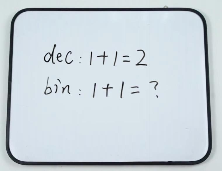
TUTORIALS Boson In mathematical operations, we often use the method is a decimal algorithm, but binary is a widely used in the calculation of a number of systems, binary data is 0 and 1 two numbers to represent the number. In decimal, we know that "1 + 1 = 2". So what is the operation in binary?
1) Logic –AND
2) Logic –OR
3) Logic –NOT
4) Logic –XOR
2. Binary Adder Schematic
DFRobot BOSON Demo Project 03- Make a Binary Half Adder
DFRobot
Jun 02 2017 699
In mathematical operations, we often use the method is a decimal algorithm, but binary is a widely used in the calculation of a number of systems, binary data is 0 and 1 two numbers to represent the number. In decimal, we know that "1 + 1 = 2". So what is the operation in binary?
1. Learn about logical operations
First, let's take a look at a few logical operations.
1) Logic –AND
Logical operation diagram:
"AND" logical truth table:
INPUT | OUTPUT | |
A | B | T |
0 | 0 | 0 |
1 | 0 | 0 |
0 | 1 | 0 |
1 | 1 | 1 |
2) Logic –OR
Logical operation diagram:
"OR" logical truth table:
INPUT | OUTPUT | |
A | B | T |
0 | 0 | 0 |
1 | 0 | 1 |
0 | 1 | 1 |
1 | 1 | 1 |
3) Logic –NOT
Logical operation diagram:
"NOT" logical truth table:
INPUT | OUTPUT |
A | Y |
0 | 1 |
1 | 0 |
4) Logic –XOR
Logical operation diagram: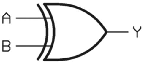
"XOR" logical operation schematic diagram:

"XOR" logical truth table:
INPUT | OUTPUT | |
A | B | Y |
0 | 0 | 0 |
1 | 0 | 1 |
0 | 1 | 1 |
1 | 1 | 0 |
2. Binary Adder Schematic
The binary adder to be produced today is the addition of two numbers, that is, two inputs "A" and "B". The output is two digits, "S" and "Co" bit. “Co” is carry, “S” is the result.
The schematic of the binary adder is shown below.
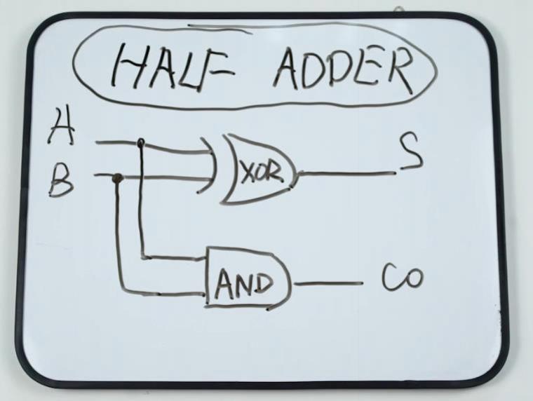
What does it mean? Do not worry, let us follow the steps below to make the binary adder. So that we know how it is the operation, so as to get the binary addition of the formula.
3. Binary Adder Required Modules and Tools
Next, we do some preparation for the production of binary adder, find the required BOSON components:
Button Module * 2
Boson Kit Main board * 1
Battery Case * 1
Boson Kit Splitter Module * 4
Logic Module-NOT* 2
Logic Module-AND* 2
Logic Module-OR * 2
LED Module * 2

4. Binary Adder Module Introduction
All modules can be divided into four categories, input modules, function modules and output modules, and Boson Kit Main board.
Input module: Button Module
Function modules: Boson Kit Splitter Module, Logic Module-NOT, Logic Module-AND, Logic Module-OR
Output module: LED Module
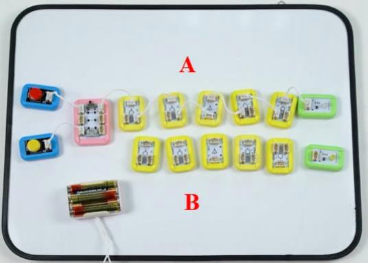
5. Wiring
We can simply see the binary adder as two paths, which are influential to each other, marked as "A" and "B".

The wiring diagram is as follows:
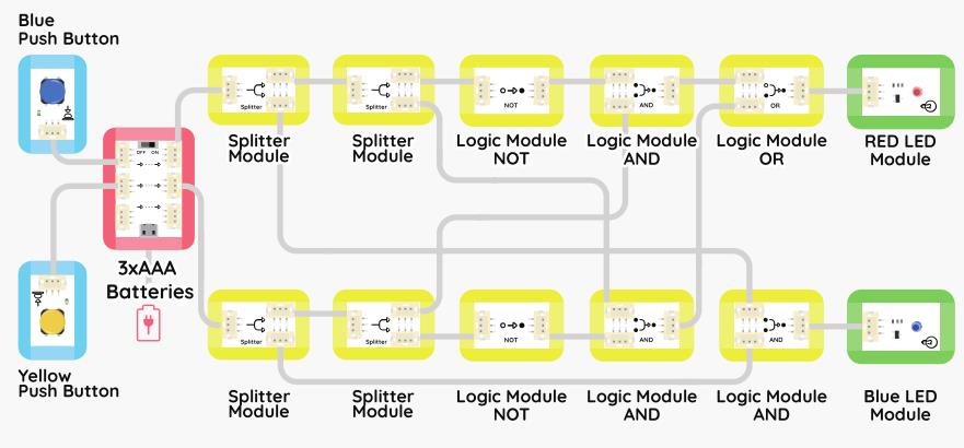
1) Use a short line to connect the input module (Button Module) to the Boson Kit Main board.

2) Connect the "A" path to the function module and the output module in a single direction, paying attention to the order and direction of each module.
3) Similar to the previous step. Connect the "B" path, but note that the part of the Logic Module-AND connected to the Logic Module-OR is connected according to the following figure.

4) We found that many of the functional modules on the interface is not connected, how can this be done?
Let's take a long line, connect the first Splitter Module in the "A" path to the Logic Module-OR in the "B" path.
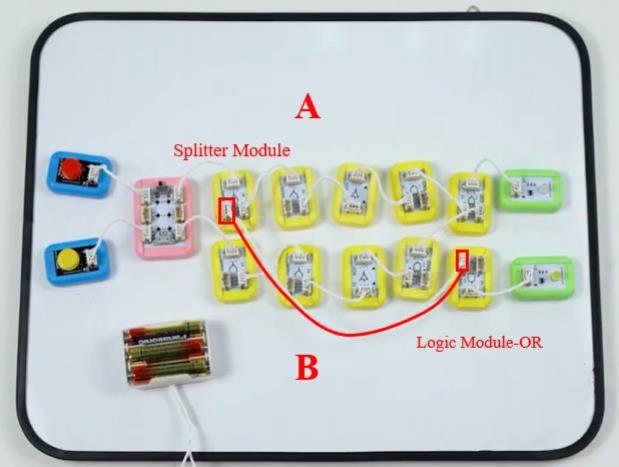
5) Use a long wire to connect the first Splitter Module to the Logic Module-OR in the "B" path.
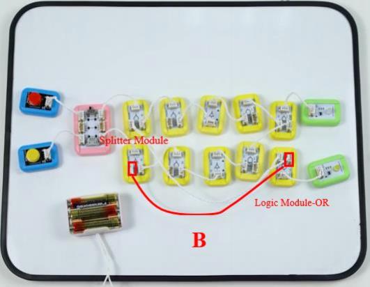
6) The second Splitter Module in the "A" path is connected to the Logic Module-AND in the "B" path with a long wire.
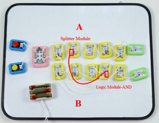
7) This is the last step!
Requires a medium-length wire. Connect the remaining two interfaces, that is the Logic Module-AND of the "A" path and the second Splitter Module in the "B" path, so that the complicated wiring part is done!

8) Let's get the power on!
Connect the Battery Case to the Boson Kit Main board and set the switch on the Boson Kit Main board to the "ON" position. You will see that the power indicator is on, indicating that it is already working.

6. Binary addition
1) When the two buttons are not pressed, all the output of the LED Module are not lit.
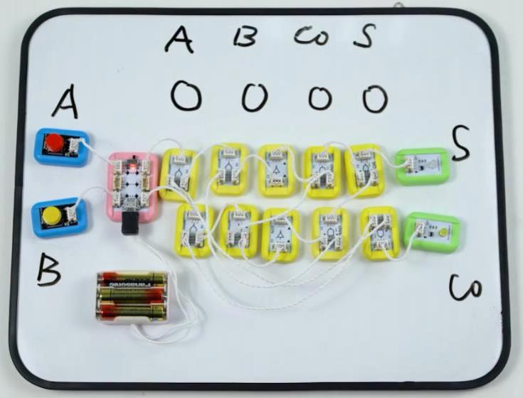
This means that the binary addition algorithm is "0 + 0 = 0".
2) When the red Button Module is pressed, it means "1", and "0" is not pressed, and the corresponding lamp at the S bit is on.
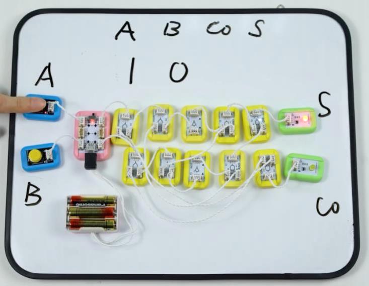
This means that the binary addition algorithm is "1+ 0 = 1".

3) When the yellow Button Module is pressed, it means "1", and "0" is not pressed, and the corresponding lamp at the “S” bit is on.
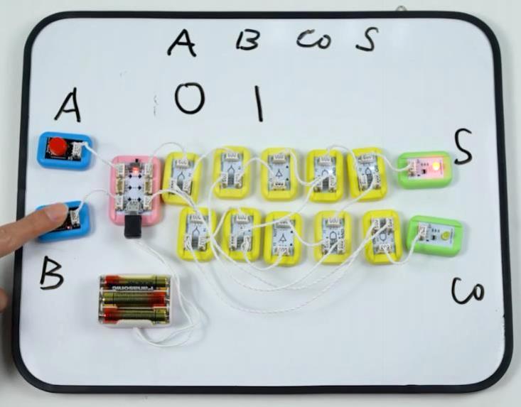
This means that the binary addition algorithm is "0+ 1= 1".
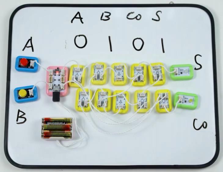
4) When the yellow the red Button Module are pressed, it means that "1" is input, and the lamp corresponding to the “Co” bit is on.
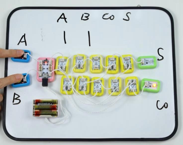
This means that the binary addition algorithm is "1+ 1= 10".
Do you know how binary addition is done?
REVIEW
Related Product

$164.00

$299.00
Recent Blogs

Essential Compatibility Insights for Raspberry Pi 5: What You Need to Know Before Purchase
Discover how to fully harness the Raspberry Pi 5's capabilities, ensuring a smooth upgrade and maximizing your tech projects’ potential.
SELECTION GUIDE Raspberry Pi Apr 19 2024

How to Select SBC (Lattepanda/Raspberry Pi) for Local LLM (LLaMA, LLaMA2, Phi-2, Mixtral-MOE, etc.)
Discover why Lattepanda Sigma is well-suited for local large language model (LLM) operations. Explore its memory and storage capacities compared to other SBCs.
SELECTION GUIDE AI Mar 29 2024

Selection Guide of Linux Systems Compatible with RISC-V Architecture
This article will provide a detailed introduction to several versions of Linux systems, including Ubuntu, Debian, Fedora, OpenSuse, FreeBSD, and OpenBSD, and the compatibility with the RISC-V architecture.
SELECTION GUIDE Mar 27 2024

 Home
Home
 Category
 Shopping Cart
 Me
Me