


TUTORIALS Arduino
You will see the LED getting brighter and fading constantly after uploading the code.
In the main code, we only use 2 functions. You will have a clear idea after checking one of them as below.

1. Create a flickering flame effect using LEDs by controlling the value of PWM at random. Cover it with paper and it will become a little lamp at night.
Related category: arduino kits > education kits
Arduino Project 4: Breathing LED
DFRobot
Apr 13 2017 4273
Related Product: Beginner Kit for Arduino
Arduino Tutorial: Breathing LED
In previous lessons, we learned how to turn a LED on and off by Arduino programming. It is also possible to control the brightness of your LED as well. There are 6 digital pins marked with “~” on your controller. This means that these pins can use a PWM signal. Today We will use arduino starter kit to build a RGB LED fader by controlling PWM creating a smooth brightening and dimmming of your LED as it gradually turns on and off.
Components:
DFRduino UNO R3 (similar as Arduino UNO R3) *3
Arduino Prototype Shield*1
Jumper Cables M/M *2
Resistor 220R*1
5MM LED*1
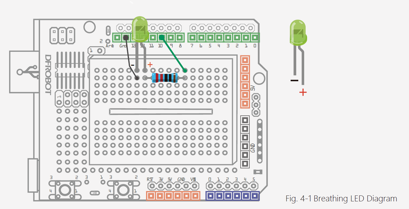
Circuit
The wiring diagram is the same as Project 1. If you are not clear about it, go back to Project 1 and have a look.
Arduino Code
You will see the LED getting brighter and fading constantly after uploading the code.
Sample Code 4-1:
// Project 4
int ledPin = 10;
void setup() {
pinMode(ledPin,OUTPUT);
}
void loop(){
fadeOn(1000,5);
fadeOff(1000,5);
}
void fadeOn(unsigned int time,int increament){
for (byte value = 0 ; value < 255; value+=increament){
analogWrite(ledPin, value);
delay(time/(255/5));
}
}
void fadeOff(unsigned int time,int decreament){
for (byte value = 255; value >0; value-=decreament){
analogWrite(ledPin, value);
delay(time/(255/5));
}
}
Code
Most of the code we are already very familiar with, such as initializing variable declarations, setting pins, setting up the for loop, as well as the function call.
In the main code, we only use 2 functions. You will have a clear idea after checking one of them as below.
void fadeOn(unsigned int time,int
increment){
for (byte value = 0 ; value <
255; value+=increment){
analogWrite(ledPin, value);
delay(time/(255/5));
}
}
The fadeOn() function has 2 parameters, “int time” for time and “int increment” for the increasing values. There is a for() statemen that repeats the program. The condition is “value < 255” and the amount of brightness increase is decided by increment.
This is a new command in the for() function.
analogWrite(ledPin, value)
How can we send analog values to a digital pin? We use pins marked with a ~ on the end, such as D3, D5, D6, D9, D10 and D11, to output a variable amount of power to the LED. These technique of controlling power is known as Pulse Width Modulation , or PWM for short.
The format of the analogWrite command is as below:
The analogWrite() function is to assign the PWM pin an analog value between 0 and 255.
Roughly every 1/500 of a second, the PWM pins outputs a pulse using digital signals. By controlling the length of on and off, it creates an equivalent effect of carrying out voltage between 0 volts and 5 volts. The length of pulse is called “pulse width” so PWM refers to pulse width modulation.
Let’s take a closer look at PWM.
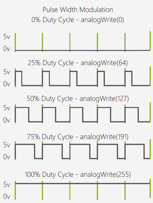
The green line is the cycle of the pulse. The percentage of length of high voltage and low voltage according to the value of analogWrite() function is known as the “Duty Cycle”. The duty cycle of the first pulse is 0. So the value is 0 and the brightness of LED is 0, equivalent to off. The longer the signal is HIGH, the brighter the LED is. The duty cycle of the last pulse is 100%. So the value is 255 and the brightness of LED is 255. Likewise, 50% is half brightness and 25 % is relatively dimmer.
PWM is widely used in controlling light brightness. We also use it to control the rotating speed of motors, such as wheels of vehicles powered by motors.
This chapter is over! Although we have used the same hardware as in Project 1, Arduino is running a different program, resulting in a completely different effect.
We think that the Arduino is amazing and we hope by now you do too!
Exercise
1. Create a flickering flame effect using LEDs by controlling the value of PWM at random. Cover it with paper and it will become a little lamp at night.
Materials:
1 red LED
2*yellow LCD
1*220 resistor
Use the “random()” command to adjust the brightness level. We suggest you to initialize a brightness level first and let it change within a random value, such as random(120)+135. This way, the LED can change within a small amount just like a real flame!
You can look up to the references below for more explanations of various commands.
https://www.arduino.cc/en/Reference/HomePage
2. Try a more challenging project: Control the LED with 2 buttons, one to make it brighter, the other to make it dimmer.
Reference: http://www.geek-workshop.com/thread-1054-1-1.html
Related category: arduino kits > education kits
Last Arduino Tutorial 3: Interactive traffic lights
Next Arduino Tutorial 5: Color RGB LED
REVIEW
Recent Blogs

Essential Compatibility Insights for Raspberry Pi 5: What You Need to Know Before Purchase
Discover how to fully harness the Raspberry Pi 5's capabilities, ensuring a smooth upgrade and maximizing your tech projects’ potential.
SELECTION GUIDE Raspberry Pi Apr 19 2024

How to Select SBC (Lattepanda/Raspberry Pi) for Local LLM (LLaMA, LLaMA2, Phi-2, Mixtral-MOE, etc.)
Discover why Lattepanda Sigma is well-suited for local large language model (LLM) operations. Explore its memory and storage capacities compared to other SBCs.
SELECTION GUIDE AI Mar 29 2024

Selection Guide of Linux Systems Compatible with RISC-V Architecture
This article will provide a detailed introduction to several versions of Linux systems, including Ubuntu, Debian, Fedora, OpenSuse, FreeBSD, and OpenBSD, and the compatibility with the RISC-V architecture.
SELECTION GUIDE Mar 27 2024

 Home
Home
 Category
 Shopping Cart
 Me
Me