PROJECTS ESP8266Arduino Hardware components
Custom PCB
Hey whats up Guys! Akarsh here from CETech.
Step 1: Parts
I would also recommend using a PCB to make some project using this module so that adding battery/OLED display/switch/esp8266 doesnt remain difficult.
Download the Arduino IDE from here
4. Go to Tools > Board > Boards Manager
1. Solder the headers on the OLED shield as well as the Micro-controller module.
2. Extract the libraries, rename them by removing the name "-master" from them.
6. Navigate to Tools > Board. Select the appropriate board that you are using, Firebeetle ESP8266 in my case.
1. Connect the module with a power supply using the micro USB connector on board or just switch on the switch if you have connected a battery.
3. When you will use the different buttons on the joystick you will see that the display in real time shows what direction have you moved the joystick in.
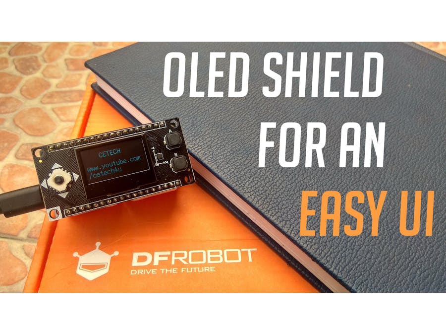
Easy to implement UI || OLED display with Joystick & buttons
DFRobot
Feb 18 2019 260220
This module has an OLED display with two buttons, 5-way joystick and a 3-axis accelerometer. This is useful in setting up UI for a project.
This project is made by Akarsh Agarwal
Things used in this project
Hardware components
DFRobot Firebeetle Covers-OLED12864 Display
DFRobot FireBeetle ESP8266 IOT Microcontroller
Custom PCB
DFRobot FireBeetle Covers-Proto Board
Hand tools and fabrication machines
Soldering iron (generic)
Story
Hey whats up Guys! Akarsh here from CETech.
Today we are going to take a look at an all in one module which is very much usefull in rigging up a quick UI hardware interface for any project that we make in the future. Watch the video on my channel to see the board in action!
Lets start with the project now.
Step 1: Parts
To make this you will need an ESP8266 board and you can also add a battery if you want.
I suggest to use a board from DFRobot with this module as the pinout will be compatible and you will face no issues anywhere, I used Firebeetle esp8266 board from DFRobot as it has on board battery charging and monitoring solution.
I would also recommend using a PCB to make some project using this module so that adding battery/OLED display/switch/esp8266 doesnt remain difficult. 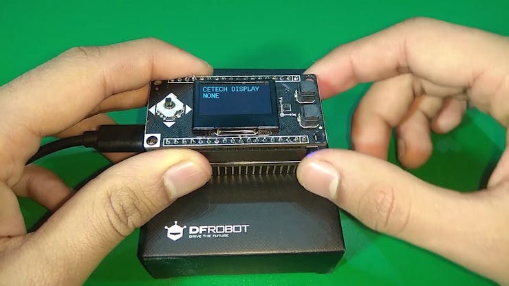
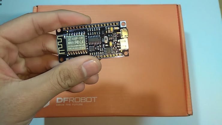
The Firebeetle board ESP8266
Step 2: Download and setup the Arduino IDE
Download the Arduino IDE from here
1. Install the Arduino IDE and open it.
2. Go to File > Preferences
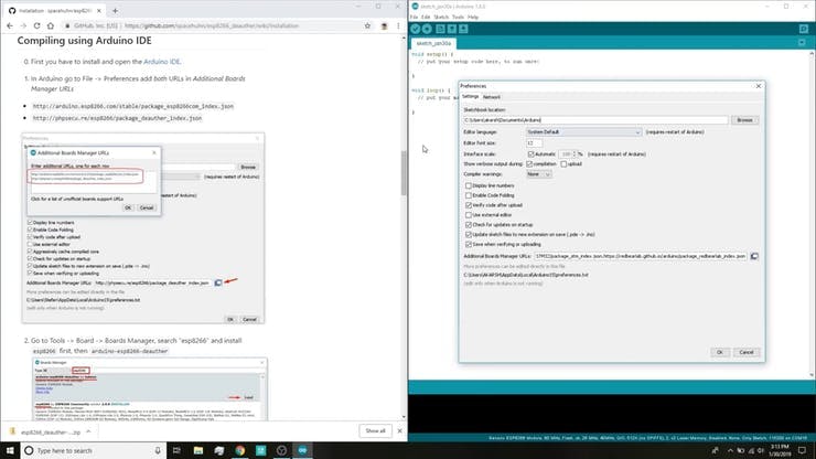
3. Add http://arduino.esp8266.com/stable/package_esp8266com_index.jsonto the Additional Boards Manager URLs.
4. Go to Tools > Board > Boards Manager
5. Search for esp8266 and then install the board.
6. Restart the IDE.
Step 3: Prepare the parts
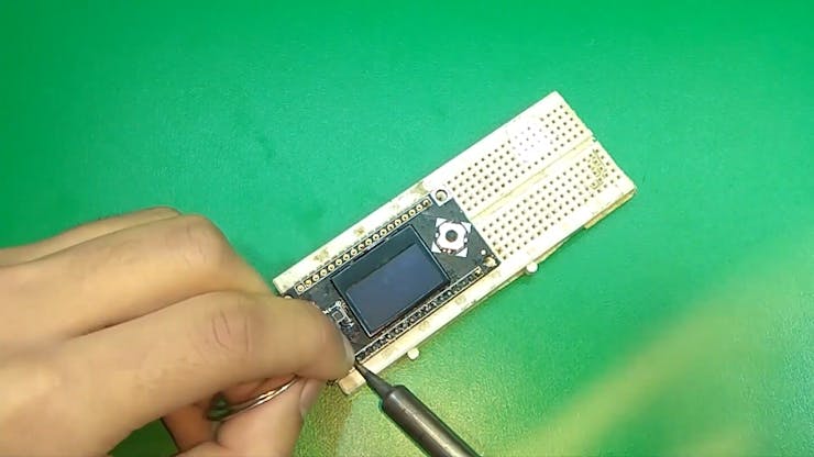
1. Solder the headers on the OLED shield as well as the Micro-controller module.
TIP: Use a breadboard to align the headers and then solder the module keeping the headers inserted into the breadboard.

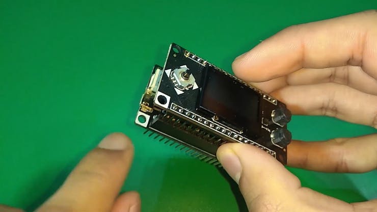
2. Align the Corners with the white colors on the on both the modules and stack them using the headers. Now connect the board to the PC.
Step 4: Coding the module
1. Download the libraries
2. Extract the libraries, rename them by removing the name "-master" from them.
3. Navigate to the libraries folder in your Arduino IDE and paste both the folders here.
4. Restart the Arduino IDE.
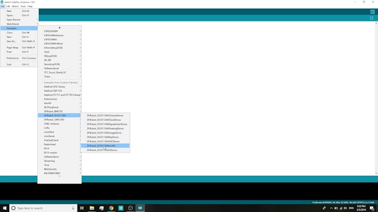
5. Navigate to File>Examples>DFRobot_OLED12864>testall and open this code.
6. Navigate to Tools > Board. Select the appropriate board that you are using, Firebeetle ESP8266 in my case.
7. Select the correct comm. port by going to Tools > Port.
8. Hit the upload button.
9. When the tab says Done Uploading you are ready to use the shield.
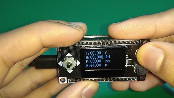
After uploading open the serial monitor to view the following details
Step 5: Playing with the shield
1. Connect the module with a power supply using the micro USB connector on board or just switch on the switch if you have connected a battery.
2. As soon as the module is connected you will see the display coming to life.

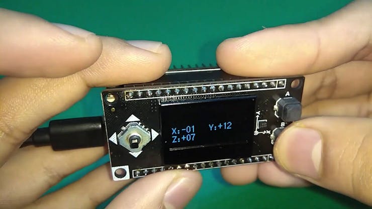
3. When you will use the different buttons on the joystick you will see that the display in real time shows what direction have you moved the joystick in.
4. Pressing the button A & B show different types of data as in the pictures below
5. CONGO! the module is working as expected.
Recent Blogs

How to Choose the Best MP3 Player Module for Your Arduino / DIY Project (2025 Selection Guide)
This guide can help you to select an MP3 module.
SELECTION GUIDE ArduinoDFRobotEnglish Sep 21 2025

How to Choose the Best CO2 Sensor for Arduino / ESP32 Project (2025 Selection Guide)
Explore the features, specifications, and applications of Gravity CO2 sensors, including electrochemical, infrared, and photoacoustic NDIR sensors. Choose the right sensor for your needs.
SELECTION GUIDE GravityArduino Sep 18 2025

Step-by-step Tutorial: Connecting FireBeetle 2 ESP32-C5 Development Board to Home Assistant Using MQTT
Follow this step-by-step tutorial to connect the FireBeetle 2 ESP32-C5 to Home Assistant using MQTT. Learn to configure the Mosquitto broker, flash your board with Arduino, and display sensor data for your smart home automation projects.
TUTORIALS ESP32IoT Aug 18 2025