I am planning on making my own high torque servo. Can this be used to drive and break the motor just like a servo controller would, I mean if I brake the motors will it hold its po...
 JaneYu 2015-09-11 23:12:04 25 Views15 Replies
 I am planning on making my own high torque servo. Can this be used to drive and break the motor just like a servo controller would, I mean if I brake the motors will it hold its position.
I see you are now shipping v1.4 of this controller, do you have an updated schematic?
JaneYu I'm trying to use this controller with Raspberry PI. Just wondering how I can have E1 & E2 enabled/disabled and at the same time, playing with PWM value to control the speed
JaneYu If you need two controlled motors at the same speed , you can connect E1 & E2 with the Radpberry Pi PWM pin. If you need two controlled motors at different speeds at the same time , you need use Radpberry Pi software PWM pin to achieve it .
The maximum operating current is 2A, while once power the motor there is a peak current normally higher the working current. When reducing the speed, the current will also reduce
JaneYu Ok, just in case someone has the same doubt as me...
The board sold in this page works in the same way the others Dual H-Bridge drives with 4-Input pins (such as the red board I posted above.)
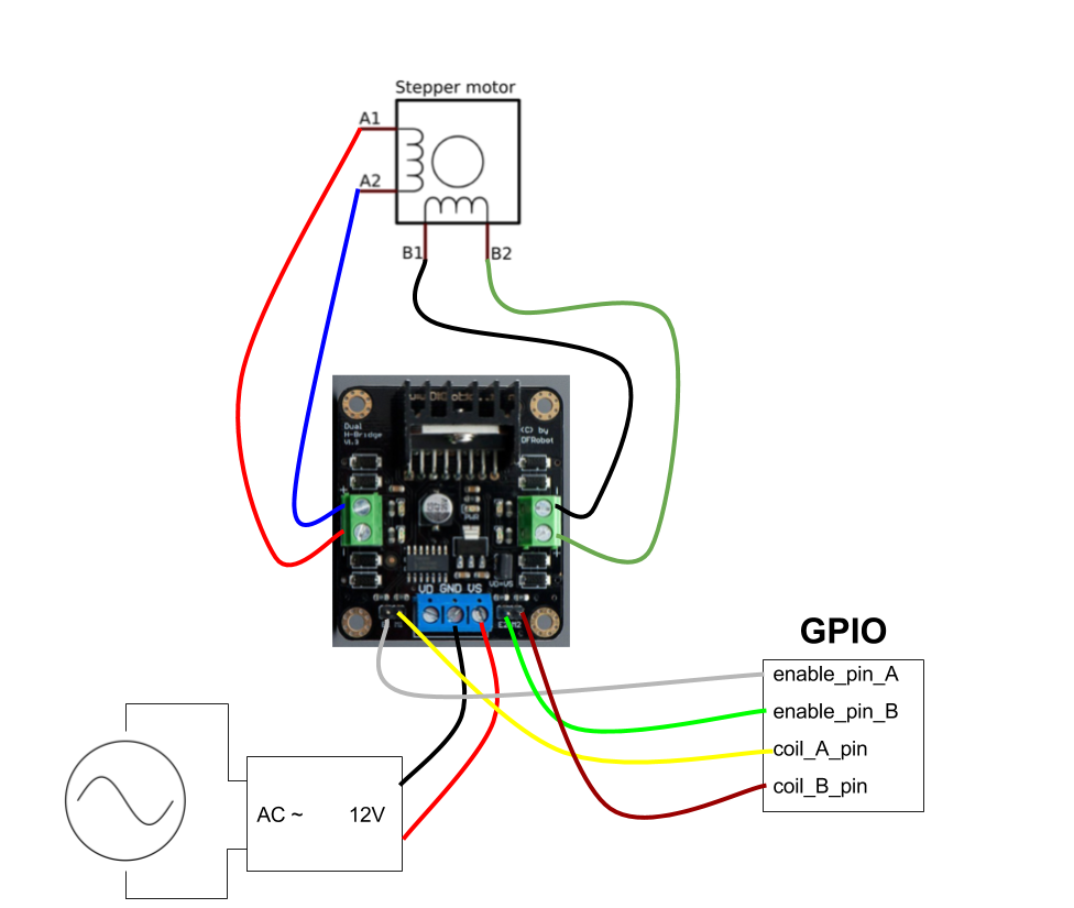
Below, you see the circuit I used.
https://uploads.disquscdn.c...
JaneYu Thanks! Matheus, that's really helpful for control a stepper motor using this module
Where are the L298n INPUT1, INPUT2, INPUT3 and INPUT4 pins in this board?
I'm trying to control a stepper motor with it, but I can't figure out where are the input pins just like in here:
https://hsto.org/getpro/hab...
JaneYu I think E1 and E2 are the input pins in this board.
Do you have the schematic of this red board?
Hello DFRobot team.I want to combine this motor shield with arduino mega and arduino usb host shield.it will fit or not?please if you know reply.Thank you for your time.
The arduino usb host shield that i want to use:
https://www.arduino.cc/en/M...
JaneYu Thanks for the graphic. What i wanted to know, is the position of the power terminals and the signal pins. My plan is to replace the connectors and stack the controller on another PCB, as can be seen in this picture: http://ep.yimg.com/ca/I/yhs...
JaneYu Xbee is PH2.0 pins and the base looks like xh2.54 ones
Is there any chance in getting the PCB layout or the dimensions of the terminal footprints? I'm planning to solder pin headers to the bottom of the PCB (instead of the temrinals) and stack it on a custom PCB. Therefore i need the positions of the standard terminals.
I could also use the given schematics and copy the whole product onto my PCB, but since i already have lots of these controllers laying around, it would be much cheaper to reuse them. Measuring with a caliper would be my last option, so any help would be appreciated.
JaneYu I'm driving just one motor, can I bridge or parallel the two output to make a 4A max current driver?
JaneYu 
