Hello, I checked mine and it is indeed reversed. The slikscreen markinds for male headers are useless.All female headers are correctly marked. But male headers markings are reverse...
 JaneYu 2023-01-19 23:48:23 55 Views3 Replies
 Hello, I checked mine and it is indeed reversed. The slikscreen markinds for male headers are useless.
All female headers are correctly marked. But male headers markings are reversed exactly like Jacques said : Pico GP2 is connected to male header labelled GP22 and so on.
Best regards
I have bought this board (PCB version V3.0) together with with a1.51” SSD1309 transparent monochrome OLED display:
https://wiki.dfrobot.com/SKU_DFR0934_Fermion_1.51Inch_128%C3%9764_OLED_Transparent_Display_with_Converter_Breakout
Nothing is working out-of-the box without any multi meter.
How to connect the FPC cable proper between board and display adapter?
Is there anywhere a picture for beginners?
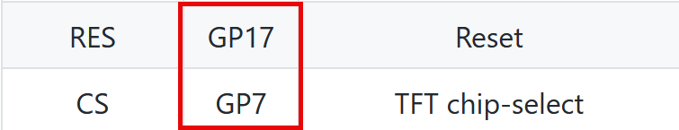
Some SPI PINs shown on the wiki page of the FPC connector are for the V3.0 PCB board version wrong:
https://wiki.dfrobot.com/PICO_Gravity_Expansion_Shield_SKU_DFR0848
Wiki:
https://uploads.disquscdn.c...
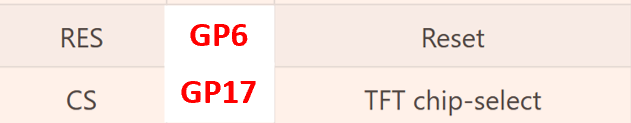
Measured and correct are the following PINs:
https://uploads.disquscdn.c...
Now it it´s working after wasting a lot of time :-(
JaneYu I have this module. It is marked as V1.0. I confirm the presence of incorrect pin marking in 2 male connectors described as:
- "Digital" - these are pins from GP2 to GP22,
- "Analog" - these are pins from GP26 to GP28.
Today I measured the resistance between the above-mentioned pins and the corresponding contacts in the RPi Pico module socket with a multimeter.
In the connector labeled "Digital", the GP2 pin should be labeled GP22, the GP3 pin should be labeled GP21, and so on down to the GP22 pin which should be labeled GP2.
In the connector labeled "Analog", the GP26 pin should be labeled GP28, the GP27 pin is labeled correctly and the GP28 pin should be labeled GP26. In this connector, the descriptions of the 2 extreme pins have been swapped.
Not all users may be aware of the incorrect pin markings in these 2 connectors. Perhaps they will try to find fault in their own electrical connections, in the source code of their programs or even in the code of library files. Some may even think that they broke something in the mentioned board or in the RPi Pico board. I think they deserve help. Therefore, DFRobot should issue an erratum to this board, e.g. as a downloadable PDF file. It is enough for the erratum to contain one page with the markings present on the board and the correct ones.
JaneYu I just got one and verified with a multimeter that the connections are correct.
JaneYu 
