New: seeMote Cube for visionOS Developers - Build physical input for Apple Vision Pro apps. Learn More ›
Raspberry Pi 3B+ Tutorial : Using a 10.1” display
Introduction
The objective of this post is to analyze a 10.1″ display for the Raspberry Pi. You can check below at figure 1 a picture of the display.
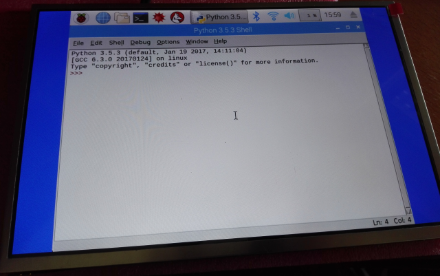
Figure 1 – Image of the display, outputting image from a Raspberry Pi.
The mentioned product is a IPS (In-Plane Switching) display with a screen resolution of 1280×800 pixels [1].It has a contrast ratio of 800:1 and a brightness of 350 cd/m^2 [1].
In terms of dimensions, the whole display has 230×149 mm, with an actual screen area of 217×135 mm [1], which means most of the display area is occupied by the actual screen.
Additionally, the display has a thickness of 5 mm and a weight of 358 g [1], making it very compact and portable.
In terms of input signal interfaces, the device supports AV, VGA and HDMI (version 1.2) [1], which means we can directly connect the Raspberry Pi to it without the need to any additional converter.
Note however that the LCD needs to be connected to a controller board, which is already included in the whole product package. We will check more on the controller board below.
In terms of power supply, it can work with a voltage between 7.5 V and 12 V [1]. Nonetheless, the product doesn’t include a power supply, which needs to be bought separately.
If you already have some transformer that can output a voltage in this range, you can use it as long as you confirm that its polarity is the same as the one the LCD uses. Additionally, you need to make sure that it can support enough current draw to power the LCD, which can only be determined by testing since the documentation of the device doesn’t state its current draw. Taking into account these factors, my recommendation is to use the power supply wall adapter recommended by the seller, to avoid damaging the LCD.
The display was tested on a Raspberry Pi 3 model B+. Nonetheless, since it has standard video input interfaces, it should be usable with other versions of the Raspberry Pi and even with other boards. One such example are the powerful LattePanda boards, which are also mentioned as supported on the product page of the display.
Where to buy
This display can be bought here, at DFRobot’s online store. The recommended power supply for the display can also be bought here.
The controller board
As already mentioned, the display needs to be connected to a controller board. The mentioned board is shown in figure 2.

Figure 2 – Display controller board.
The actual display is connected to this controller board using two different connectors (the one in the bottom center and the on the right).
Additionally, the controller board is connected to another small PCB which contains some keys that are used to control the LCD (the left connection). This PCB is shown below at figure 3.

Figure 3 – PCB board with the keys to control the LCD.
We will see in greater detail below the functionalities that can be controlled using this keys.
The power supply is also connected to the LCD controller board, which is responsible to supply the display. We also connect the Raspberry (or the other device used) to this board using one of the 3 available interfaces (HDMI, AV or VGA).
You can check below at figure 4 an image of the controller board with the different peripherals connected to it highlighted.

Figure 4 – Connection of peripherals to the LCD controller board.
It’s important to mention that the display and the keys PCB board already have cables with interfaces ready to connect to the controller board, which means that no soldering is required and the connections are simple.
What needs special attention are the display connections since they have less connectors than the pins of the controller board. So we need to put them in the correct positions, as indicated in figure 4.
To make sure you perform all the correct connections, please download the installation instructions PDF file available at the product description page, which has more detailed images of all the connection steps.
You can check below at figure 5 the whole system after the connections are performed.
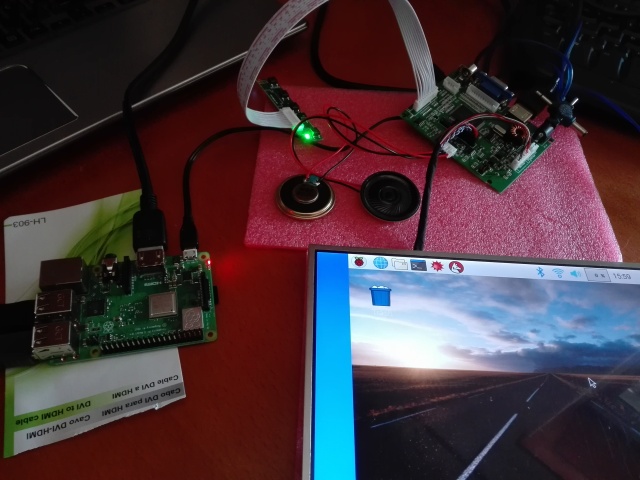
Figure 5 – Whole system after performing all the connections.
The keys and functionalities
As already mentioned, the controller board is connected to a smaller PCB which contains some keys to control the LCD. These keys basically correspond to the typical interface many monitors have, with a couple of buttons to turn it on, off or control parameters such as brightness.
So basically, for this LCD, we have a button to turn on and off the display. The LED present on that board changes between red and green, depending if the display is off or on, respectively.
Then, we have a menu button that, when clicked, opens an interface like the one shown on figure 6, which allows to adjust some parameters of the display.

Figure 6 – Display menu.
We also have two buttons to control the volume. If we click them, we get a volume bar like the one shown in figure 7, for an easier adjustment.
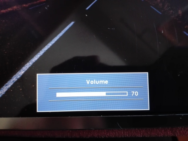
Figure 7 – Volume adjustment interface.
Finally, we have a button that allows to change between the supported input interfaces. If, after connecting your device to the display you get a “No signal” message, then most likely you need to click that button to change the input interface to the correct one.
Final notes
The analyzed display is a nice addition to be used with a Raspberry Pi. It is a compact solution that can even be used with other mini computers similar to the Raspberry Pi. Even though it requires some additional connections other than the HDMI one, it should be easy enough to get started.


Compare six 4K USB cameras using IMX415, IMX274, and IMX678 sensors across resolution, color, field of view, distortion, Linux, and low-light tests.
REVIEWS
This article is an engineering test note, mainly intended to demonstrate the actual performance of the module in common development scenarios, rather than a laboratory calibration report.
REVIEWS
Visit DFRobot at FAB26 Boston for hands-on AI workshops, open-source hardware demos, and practical insights into K–12 maker education.
NEWS