


Intel® Edison Hands-on Day 4: Touch Switch
Touch Switch
Just using the button to control the light seems not cool enough. In this section we will try a touch sensor and a relay to control the LED. Let’s make it!
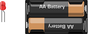
Components required


- LED (or other output device) and the corresponding power supply
Connection
Capacitive Touch Sensor → Digital Pin 2
Relay Module → Digital Pin 12

Notice that relay can be considered as a electrically controlled switch. You can even use it to control the electrical appliances with high voltage and high current in your home. For the sake of safety, however, we would recommend NOT to hack in the high voltage stuffs at the first time.
How to use relay?
Let’s talking about the relay. You can use a digital pin to directly control the switch.
There is four out connections in this relay module, which is COM(Common), NO(Normally Open), NC(Normally Closed), N/A(Not applicable)

COM = Common, NC and NO always connect to this pin, it is the moving part of the switch.
NC = Normally Closed, COM is connected to this when the digital pin is LOW.
NO = Normally Open, COM is connected to this when the digital pin is HIGH.
Coding
int touchPin = 2; //The pin of the touch sensor
int relayPin = 12; //The pin of the relay
int relayState = HIGH; // relayState stores the state of relay
int touchState; // touchState stores the state of touch sensor
int lastTouchState = LOW; // lastTouchState stores the last state of touch sensor
long lastDebounceTime = 0;
long debounceDelay = 50; // debounce time
void setup() {
pinMode(touchPin, INPUT);
pinMode(relayPin, OUTPUT);
digitalWrite(relayPin, relayState);
}
void loop() {
//read the touch sensor state into the reading variable.
int reading = digitalRead(touchPin);
// if the state of touch sensor changes, stamp the time.
if (reading != lastTouchState) {
lastDebounceTime = millis();
}
// Wait 50ms to confirm the change really happens
// If the new state of the touch sensor is HIGH, then change the state of the relay.
if ((millis() - lastDebounceTime) > debounceDelay) {
if (reading != touchState) {
touchState = reading;
if (touchState == HIGH) {
relayState = !relayState;
}
}
}
digitalWrite(relayPin, relayState);
// record the last state of the touch sensor
lastTouchState = reading;
}
After uploading the sketch, and you can touch the sensor to control the LED.
Principle?Digital Input—Digital Output?
Apparently, touch sensor is the input device, while the relay is the output one. Meanwhile, the relay can control other devices.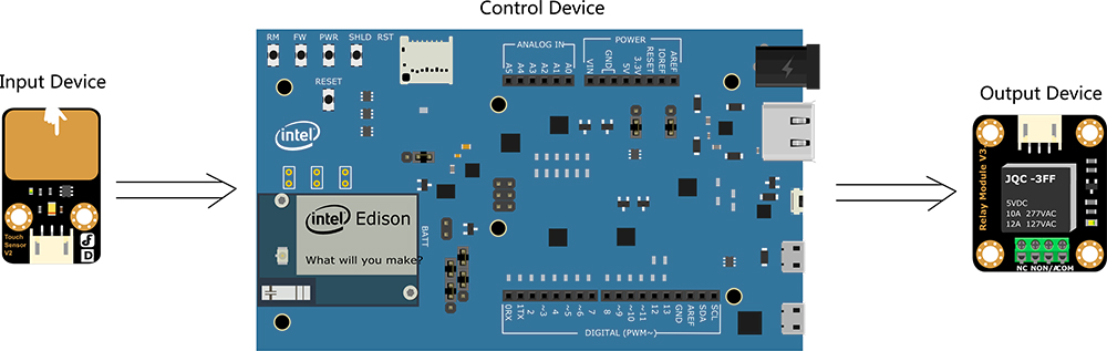
Code review
Set the touch sensor to input and the relay to output
pinMode(touchPin, INPUT);
pinMode(relayPin, OUTPUT);
use digitalWrite() to read the state of the touch sensor:
int reading = digitalRead(touchPin);
When you push the button, they may be bounce apart one or more times before making steady contact in a short time. Just like the illustration: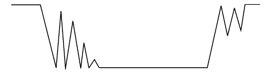
Without debouncing, pressing the button once can appear to the code as multiple presses. Makes use of the millis() function to keep track of the time when the button is pressed.
if the state of touch sensor changes, stamp the time via millis() function?
if (reading != lastTouchState) {
lastDebounceTime = millis();
}
millis() returns the number of milliseconds since the Arduino board began running the current program.
Wait 50ms to confirm the change really happens. If it really happens, change the state of the relay. In
if ((millis() - lastDebounceTime) > debounceDelay) {
if (reading != touchState) {
touchState = reading;
if (touchState == HIGH) {
relayState = !relayState;
}
}
}
REVIEW

Discover how to run YOLOv8n on the Unihiker hardware platform in this comprehensive tutorial. Learn to set up the environment, install essential libraries, and optimize performance using ONNX format.
TUTORIALS AI
Discover the top 8 TinyML frameworks like TensorFlow Lite, Edge Impulse, PyTorch Mobile, and more, to deploy advanced ML algorithms on low-power, resource-constrained devices.
NEWS AI
The newly released Jetson Copilot has attracted a lot of attention. Through this review based on the Jetson Orin 64GB platform, we will have a comprehensive understanding of the functions and performance of Jetson Copilot and its potential in practical applications.
REVIEWS AI
 Home
Home
 Category
 Shopping Cart
 Me
Me