New: seeMote Cube for visionOS Developers - Build physical input for Apple Vision Pro apps. Learn More ›
PROJECTS ESP32
Application Tutorials of FireBeetle Board - ESP32 BLE: Smarten a Plugboard
DFRobot
Jul 11 2017 262965

Come to see! A new DIY from Chocho~


Yes! What you have seen is a smart plugboard that converted by ESP32 master board and controlled by BLE of ESP32. As a fan of Arduino, I am worried about that ESP32 has been supporting Wi-Fi and Bluetooth but without libraries files for Arduino. However, the smart plugboard can control many slave equipment at the same time. Trust me, I have made two and tested them.
Am I the first one to DIY with BLE of ESP32?
The video is a little bit long; please see the following steps to the details of working process.
Hardware in need:
2. FireBeetle ESP32 IOT Microcontroller (Supports Wi-Fi & Bluetooth)
5. Gravity: Digital 5A Relay Module
6. Beetle BLE
7. Button
8. Crust printed by 3D
Working Process:1. Take a power adaptor and used plugboard apart.
You would better use tweezers or nippers to break the power adaptor. Mine power adaptor used glues not screws to compound and it is very hard to take it apart.

Talking about how to take the used plugboard apart, you can refer to the video. Anyway, different factories produce different plugboards.


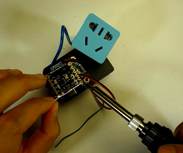
2. Make power cables.You need to find a length of household wire, no requirement of types and demolish the outer enameled wires that are about 10cm.


(1)Solder the AC power line wire.Solder one segment wire to the entry of AC.Caution: To avoid leaking, no too many solders.
(2) After the soldering, you should use a diagonal nipper to remove the USB power-supply interface.
(3) Then, you should solder a power cable to supply the FireBeetle board.

3. Connect the board.The Circuit Diagram is as below:D2 controls a relay, D3 controls RGB.
In this step, you should fix the relay, Beetle BLE board, plugboard.You can refer to the radio for details.


4. Complete machine assembly.Fix the plug with solders and put it into the crust.
Moreover, this is the end.
Come to see! A new DIY from Chocho~
Yes! What you have seen is a smart plugboard that converted by ESP32 master board and controlled by BLE of ESP32. As a fan of Arduino, I am worried about that ESP32 has been supporting Wi-Fi and Bluetooth but without libraries files for Arduino. However, the smart plugboard can control many slave equipment at the same time. Trust me, I have made two and tested them.
Am I the first one to DIY with BLE of ESP32?
The video is a little bit long; please see the following steps to the details of working process.
Hardware in need:
2. FireBeetle ESP32 IOT Microcontroller (Supports Wi-Fi & Bluetooth)
5. Gravity: Digital 5A Relay Module
6. Beetle BLE
7. Button
6. Beetle BLE
7. Button
8. Crust printed by 3D
Working Process:
1. Take a power adaptor and used plugboard apart.
You would better use tweezers or nippers to break the power adaptor. Mine power adaptor used glues not screws to compound and it is very hard to take it apart.
Talking about how to take the used plugboard apart, you can refer to the video. Anyway, different factories produce different plugboards.
2. Make power cables.
You need to find a length of household wire, no requirement of types and demolish the outer enameled wires that are about 10cm.
(1)Solder the AC power line wire.
Solder one segment wire to the entry of AC.
Caution: To avoid leaking, no too many solders.
(2) After the soldering, you should use a diagonal nipper to remove the USB power-supply interface.
(3) Then, you should solder a power cable to supply the FireBeetle board.
3. Connect the board.
The Circuit Diagram is as below:
D2 controls a relay, D3 controls RGB.
In this step, you should fix the relay, Beetle BLE board, plugboard.
You can refer to the radio for details.
4. Complete machine assembly.
Fix the plug with solders and put it into the crust.
Moreover, this is the end.
Recent Blogs

Hands-On Test of 6 New 4K USB Cameras: Resolution, Color, Field of View, and Compatibility
Compare six 4K USB cameras using IMX415, IMX274, and IMX678 sensors across resolution, color, field of view, distortion, Linux, and low-light tests.
REVIEWS Jul 23 2026

Fermion BMI323 6-Axis IMU Engineering Test Notes: Accelerometer, Gyroscope, Step Counter, and I2C Address Verification
This article is an engineering test note, mainly intended to demonstrate the actual performance of the module in common development scenarios, rather than a laboratory calibration report.
REVIEWS Jul 15 2026

Meet DFRobot at FAB26 Boston 2026: AI, Open-Source Hardware & Maker Education
Visit DFRobot at FAB26 Boston for hands-on AI workshops, open-source hardware demos, and practical insights into K–12 maker education.
NEWS Jul 15 2026