PROJECTS Raspberry Pi 2WD miniQ Robot Chassis
Arduino IDE
Controller
Raspberry Pi 3 Project: SPy Robot
DFRobot
Nov 13 2017 261511
This raspberry pi 3 project allows you to drive a robot via a webpage and view a livestream. It can be used to spy on pets, make sure nothing is burning in your oven, and even bird watch!
THINGS USED IN THIS PROJECT
2WD miniQ Robot Chassis
Texas Instruments Dual H-Bridge motor drivers L293D
Jumper wires (generic)
5v Regulator
1800 mAh 11.7V LiPo Battery
ESP8266 Thing - Dev Board
SparkFun Pushbutton switch 12mm
DFRobot Raspberry Pi 3
DFRobot Raspberry Pi Camera Module
Software apps and online services:
Arduino IDE
Hand tools and fabrication machines:
3D Printer
The Robot Electronics
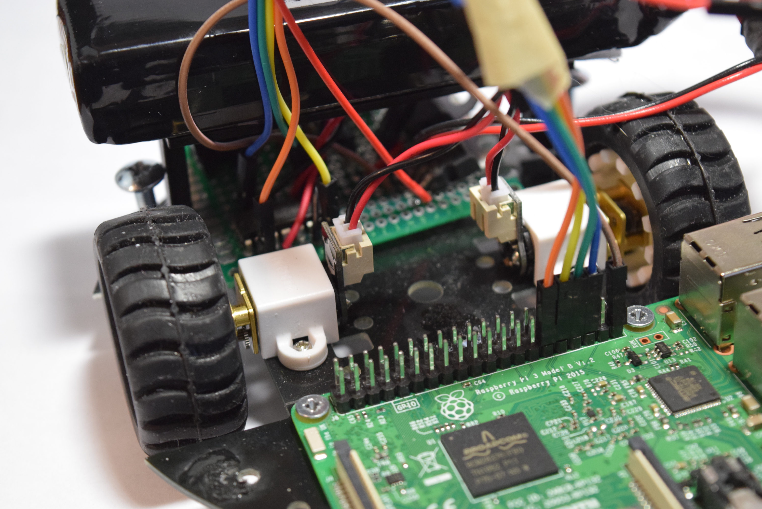
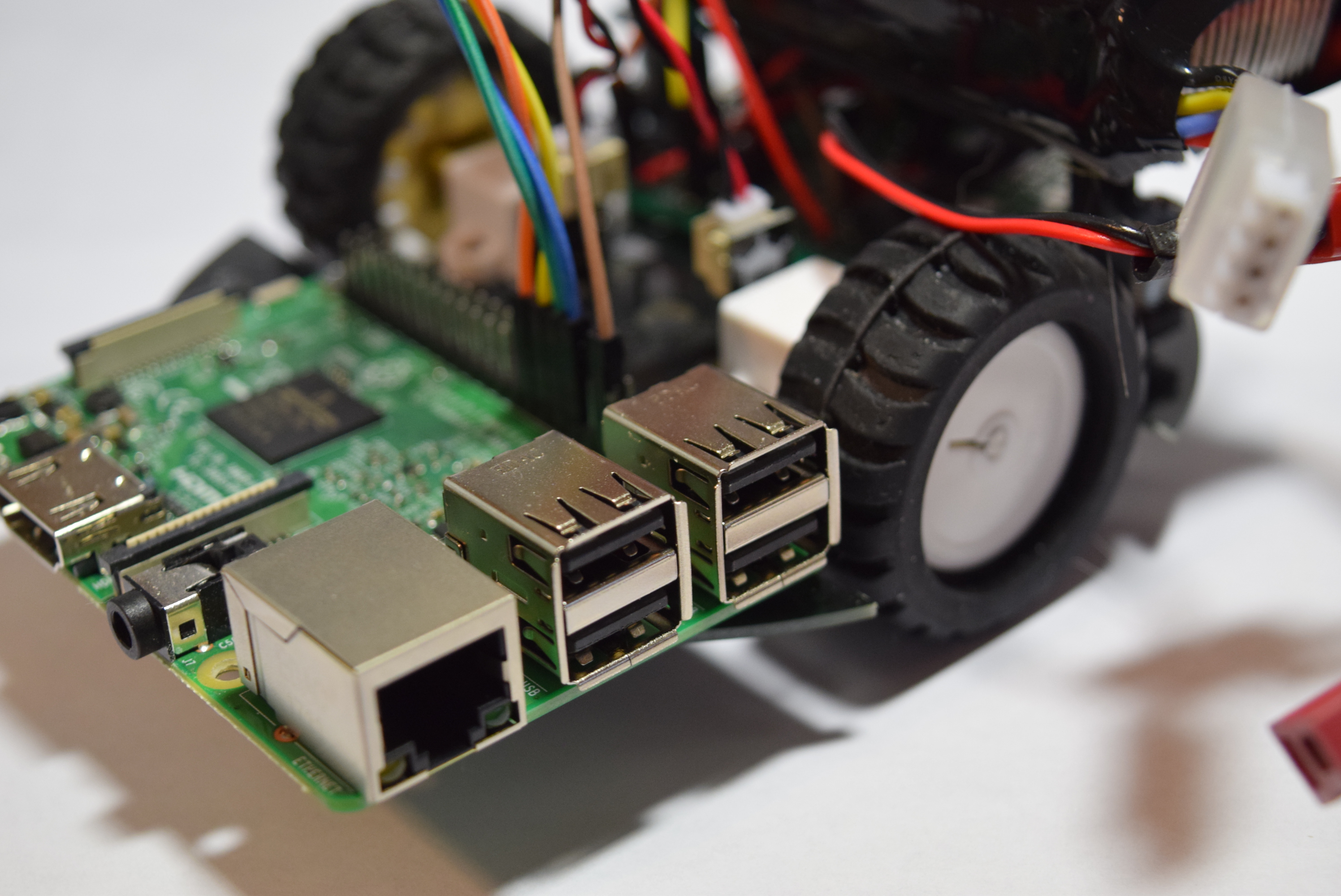
I began by assembling the 2WD MiniQ chassis kit from DFRobot. I slid the wheels onto the motor shafts, then inserted them into brackets and attached them to the chassis. Finally, I added the metal supports.
Now it was time to build the main board. The L293d motor driver got soldered in place, along with wires running to the Raspberry Pi's GPIO pins. Next, I soldered a connector for the battery, as that will provide the main power. After the power source was added, I installed a 5V regulator.
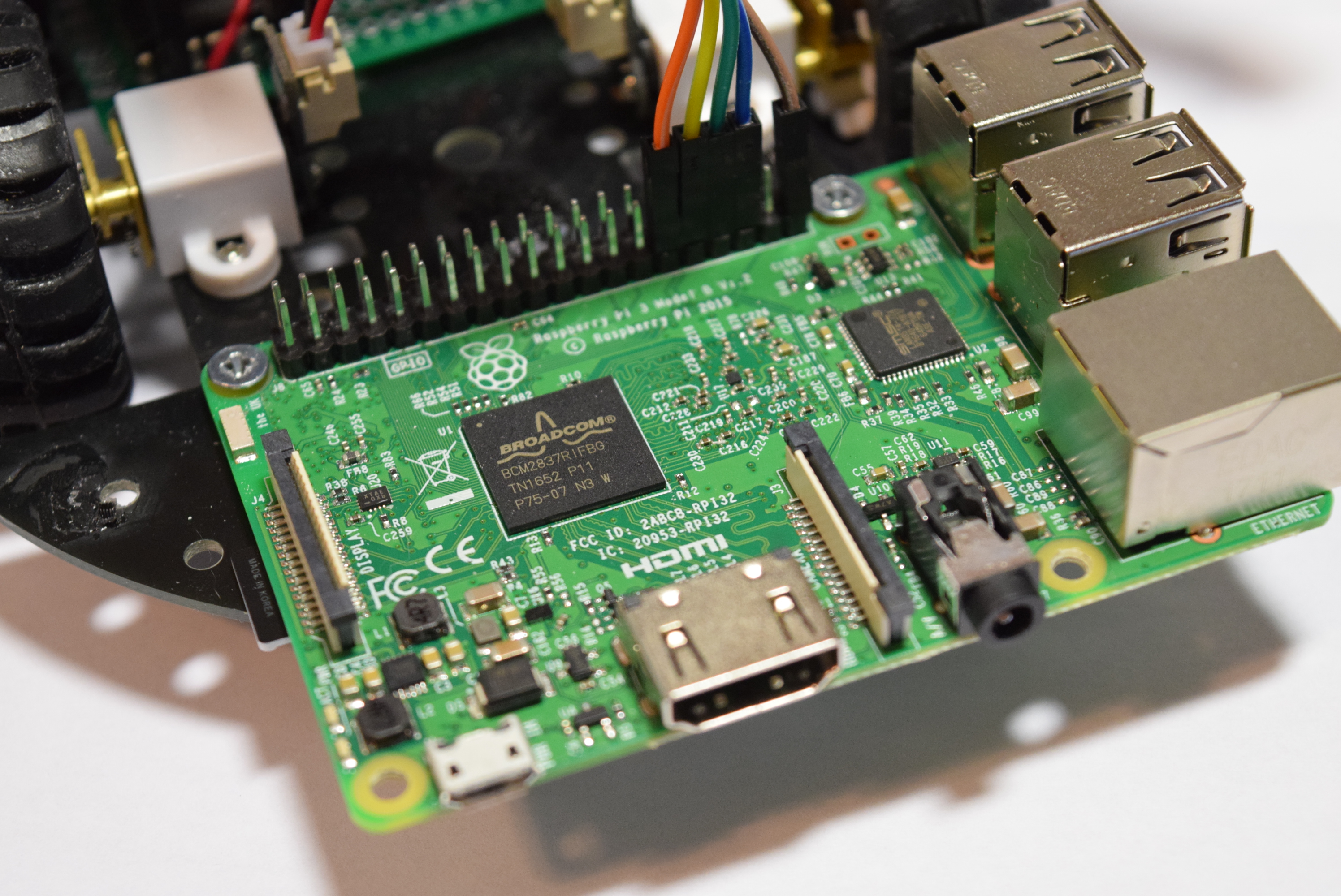
Setting Up the Pi
DFRobot reached out to me and sent their Raspberry Pi 3 and Raspberry Pi Camera Module. So after I opened up the boxes I got right to work by setting up the SD card. First I went to the Raspberry Pi Downloads page and downloaded the most recent version of Raspbian. I then extracted the file and put it into a convenient directory. You can't just copy/paste a .img file to an SD card, you have to "burn it" onto the card. You can download a burning utility like Etcher.io to easily transfer the OS image. After the .img file was on my SD card I inserted it into the Raspberry Pi and gave it power. After about 50 seconds I unplugged the cord and removed the SD card. Next I put the SD card back into my PC and went to the "boot" directory. I opened up notepad and saved it as a blank file named "ssh" with NO extension. There was also a file I added called "wpa_supplicant.conf" and put this text into it:
network={ ssid=<"SSID"> psk=<"PASSWD"> }
Then I saved and ejected the card and put it back into the Raspberry Pi 3. This should now allow for the usage of SSH and connecting to WiFi.
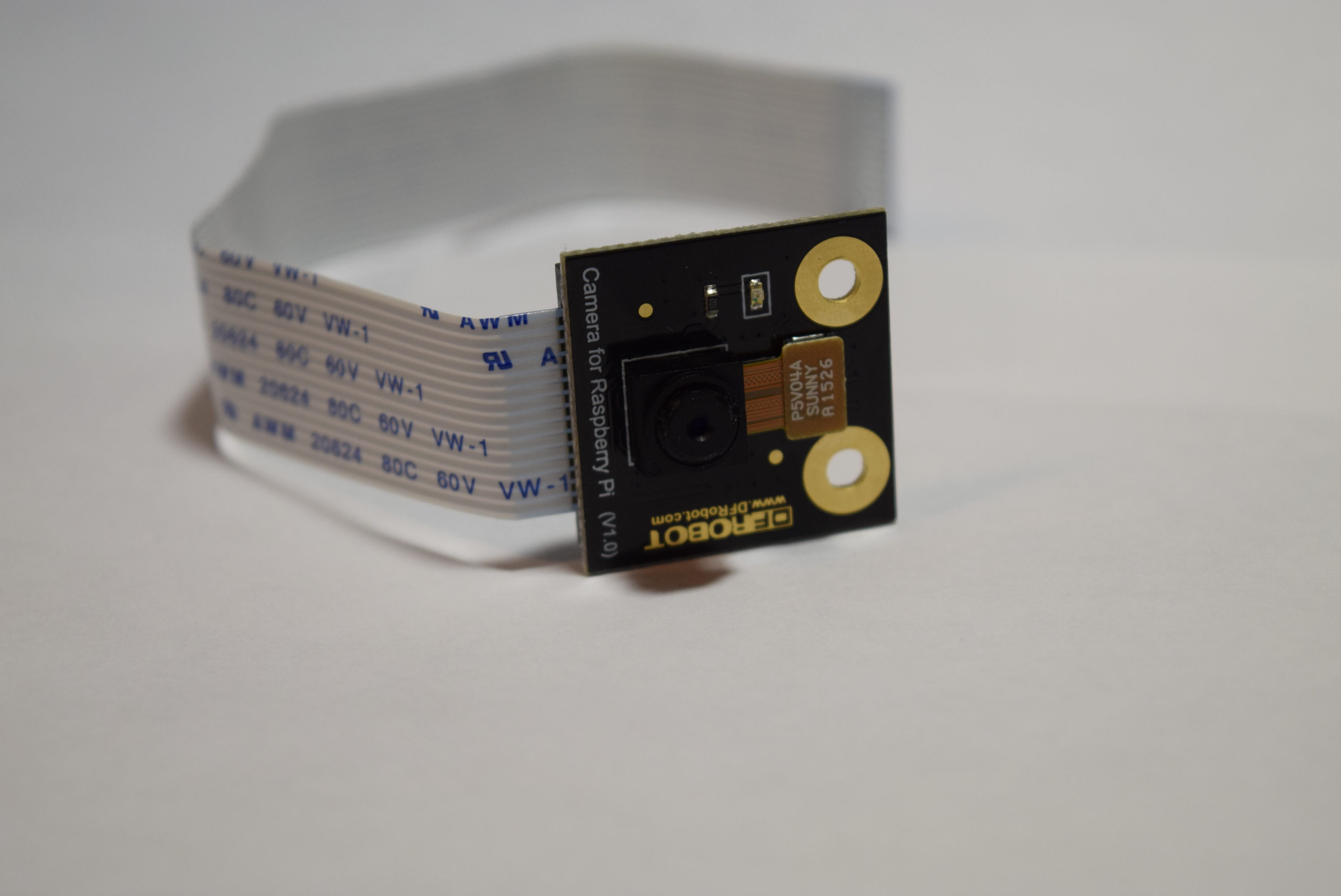
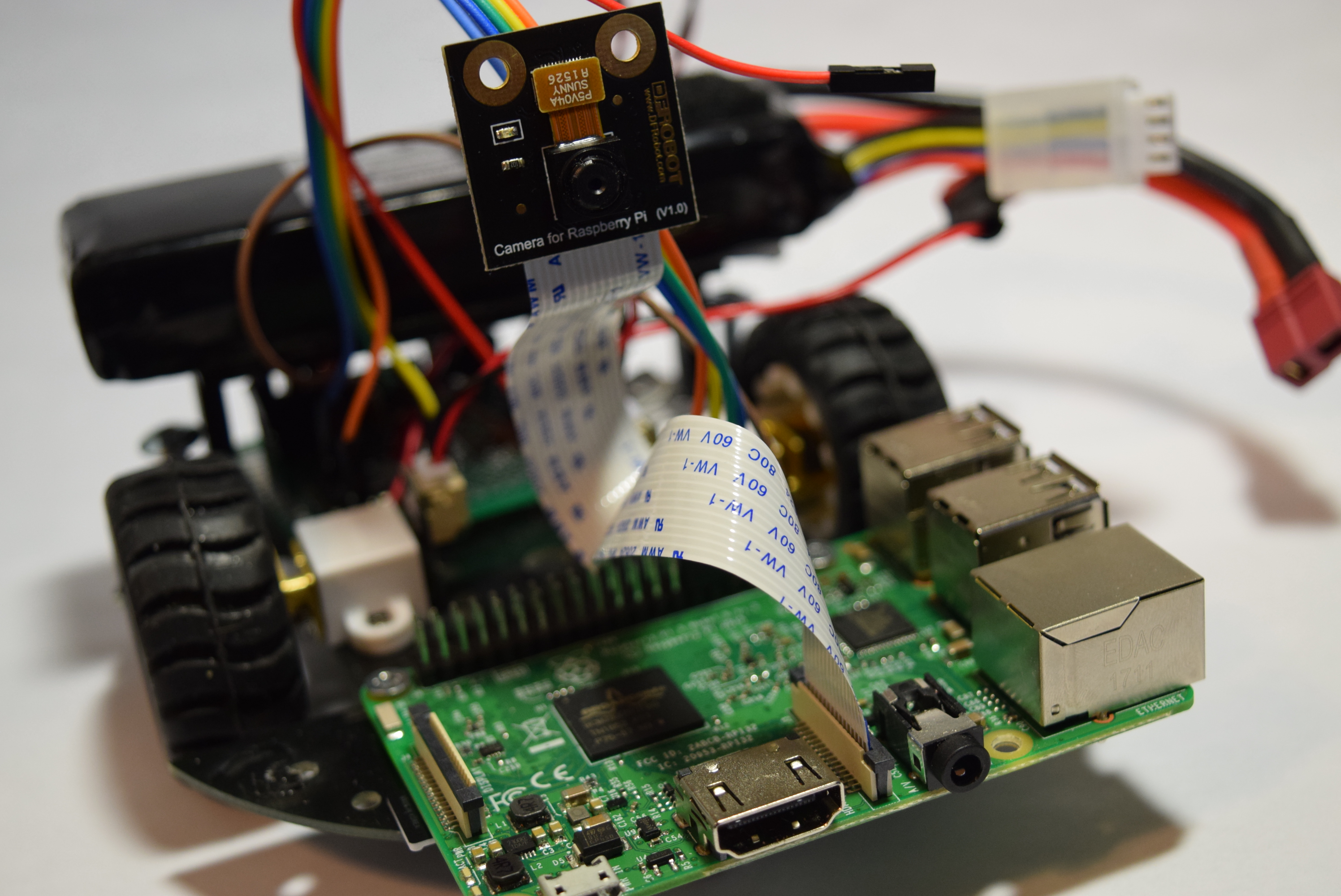
Getting the Camera Ready
By default, the camera is disabled on the Pi, so you must open the terminal type sudo raspi-config to bring up the menu. Go to "interfacing options" and then enable the camera. Now just select "Finish" and insert the ribbon cable of the camera module into the correct area of the Pi.
Installing Software
There are several different softwares that can stream video, such as vlc and motion, but I decided to use the mjpeg-streamer due to its low latency and easy installation. According to the instructions on the site, do a git clone https://github.com/jacksonliam/mjpg-streamer.git into a folder, then type sudo apt-get install cmake libjpeg8-dev to install the needed libraries. Change your directory into the folder you downloaded and then type make followed by sudo make install to compile the software. Finally enter export LD_LIBRARY_PATH=. and to run it type ./mjpg_streamer -o "output_http.so -w ./www" -i "input_raspicam.so" You can access the stream by heading to http://<The Pi's Local IP>:8080/stream.html to view the stream.
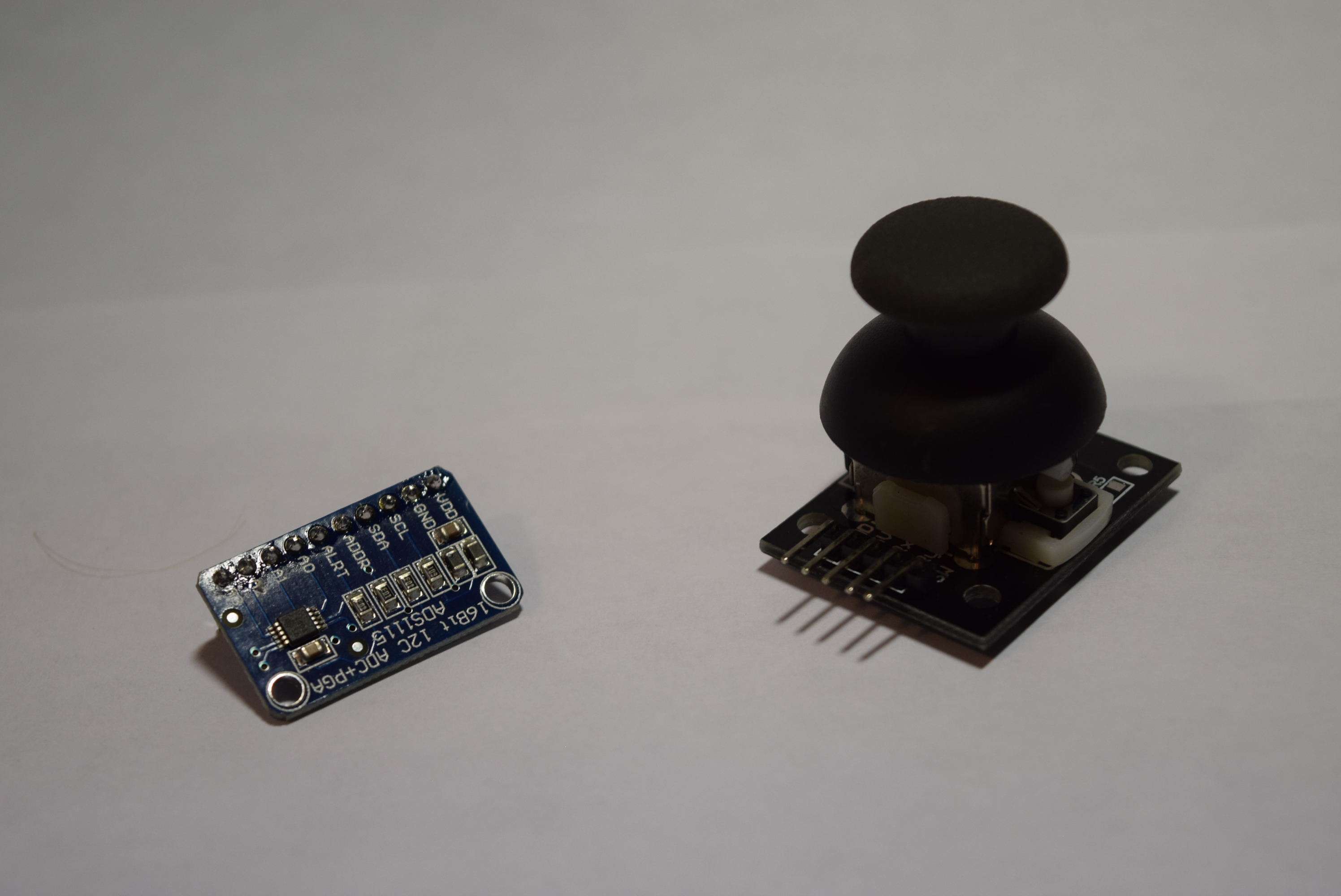
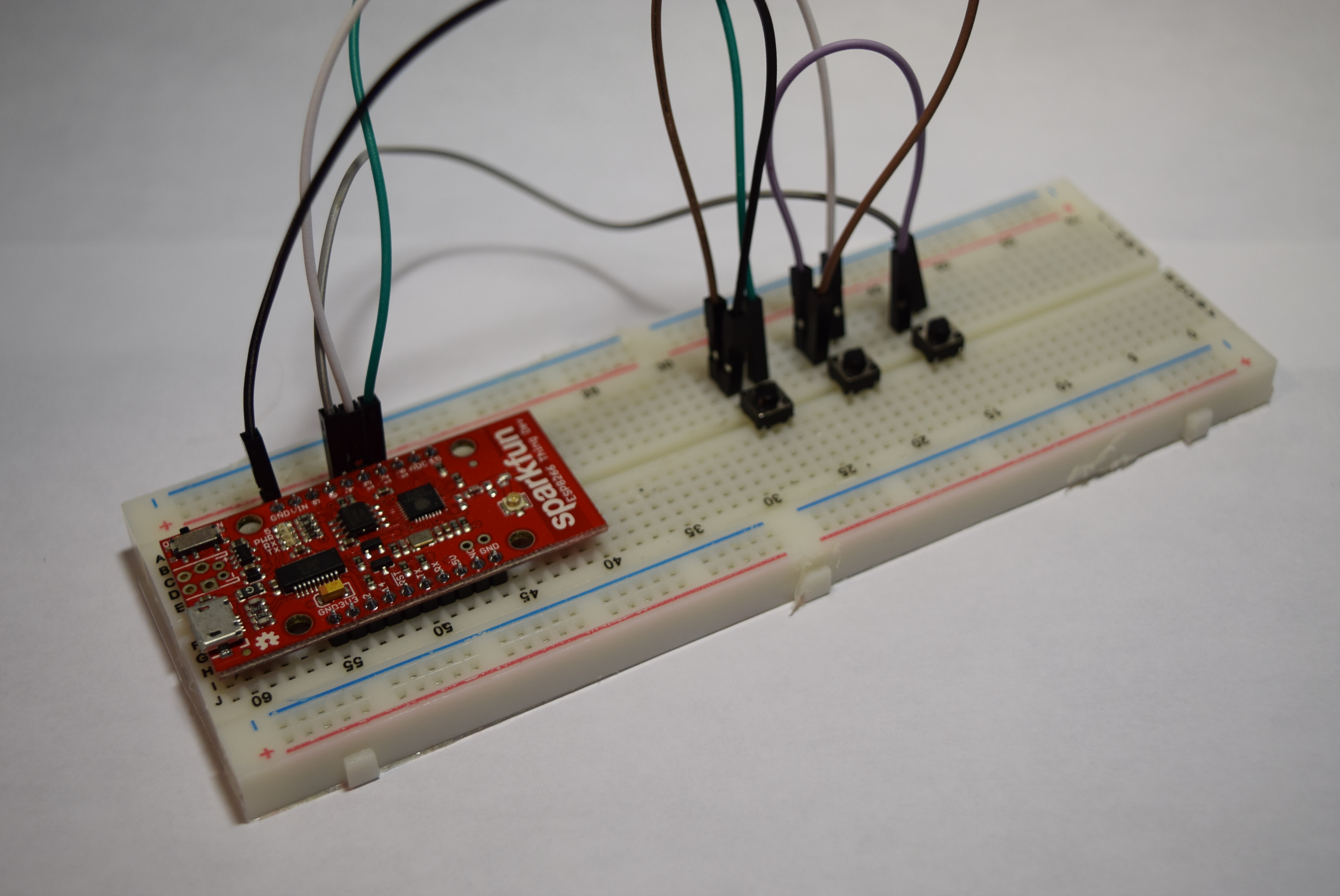
Controller
Then came the part of how to control a Raspberry Pi over WiFi, because Bluetooth has too little range. I decided on using a Flask server running on the Raspberry PI and an ESP8266 ESP12E module to send data to it. The ESP8266 only has one analog input, which means I couldn't use the joystick directly, as it takes two analog inputs. The best option was the ADS1115, which is an I2C device that reads analog signals at 16 bits of resolution. I simply connected SDA to 4 and SCL to 5, along with VCC and GND. The joystick X axis connects to A0 on the ADS1115, and the Y axis connects to A1. BUT, I accidentally burned out the ADS1115, so I had to resort to the next-best thing: buttons! So now my setup is an ESP8266 Sparkfun Thing Dev Board with 3 buttons- forward, right, and left. Now whenever one is pressed, it sends data to turn the wheels in that direction.
The Code for the Robot
I made a previous project that utilized the Pi's GPIO PWM library to control motors via json, so I just re-purposed the code to accept data via a Flask app instead. Flask is a Python library that essentially turn your Pi into a webserver capable of sending and receiving data. By using PWM, the motors can be controlled with greater precision compared to tank drive. This also means the robot can go at variable speeds rather than a fixed one. My flask app is configured to change the PWM of the motors once it receives data from a GET request via http from the ESP12e. It also uses the subprocess.Popen library to run the webstreaming script in the background. I have attached code to the project page, so all that is necessary is a download.
Controller Code
The code was pretty simple, just take readings from the 3 pins, run them through some if statements to determine wheel direction, and finally send those values to the Raspberry Pi. The ESP8266 board addition for the Arduino IDE comes with the HTTPClient library, which handles headers and sending data. The Flask server needs to receive data via a POST call, so the code starts a connection with the Raspberry Pi webserver, then adds a header to the data denoting that it's JSON encoded, and finally it sends the data in the form of a JSON object. I added a 40 ms delay to prevent the Raspberry Pi from becoming overloaded with data.
Running the Raspberry SPy
All that is required is typing sudo python <raspberryspycode>.py ! You should see the camera light up, and by going to the web address of the pi with the port 8080 the stream should be visible. Now you can use the controller anywhere in the house and have a live feed as well.
SCHEMATICS
CODE
#include <Arduino.h>
#include <ESP8266WiFi.h>
#include <ESP8266WiFiMulti.h>

#include <ESP8266HTTPClient.h>

ESP8266WiFiMulti WiFiMulti;

#define SSID "SSID"
#define PSSWD "PASSWORD"

int pins[3] = {12,13,4};

void setup() {
  // put your setup code here, to run once:
  Serial.begin(9600);
  for(int i=0; i<3;i++){
    pinMode(pins[i], INPUT_PULLUP);
  }
  WiFiMulti.addAP(SSID, PSSWD);
}

void loop() {
  // put your main code here, to run repeatedly:
  int motor1, motor2;
  if(digitalRead(pins[0])==0){ //Turn left
    Serial.println("left");
    motor1 = 50;
    motor2 = 50;
  }
  else if(digitalRead(pins[1])==0){ //Go forward
    Serial.println("forward");
    motor1 = 50;
    motor2 = -50;
  }
  else if(digitalRead(pins[2])==0){ //Turn right
    Serial.println("right");
    motor1 = -50;
    motor2 = -50;
  }
  else{
    motor1 = 0;
    motor2 = 0;
  }

  if(WiFiMulti.run() == WL_CONNECTED){
    HTTPClient http;
    http.begin("http://<RaspberryPiIP:5000/control/");
    http.addHeader("Content-Type", "application/json");
    int httpCode = http.POST("{\"motor1\":"+String(motor1)+", \"motor2\":"+String(motor2)+"}");
    String payload = http.getString();
    Serial.print('\t');
    Serial.println(httpCode);
    Serial.println(payload);
  }
  delay(40);
}
Recent Blogs

Hands-On Test of 6 New 4K USB Cameras: Resolution, Color, Field of View, and Compatibility
Compare six 4K USB cameras using IMX415, IMX274, and IMX678 sensors across resolution, color, field of view, distortion, Linux, and low-light tests.
REVIEWS Jul 23 2026

Fermion BMI323 6-Axis IMU Engineering Test Notes: Accelerometer, Gyroscope, Step Counter, and I2C Address Verification
This article is an engineering test note, mainly intended to demonstrate the actual performance of the module in common development scenarios, rather than a laboratory calibration report.
REVIEWS Jul 15 2026

Meet DFRobot at FAB26 Boston 2026: AI, Open-Source Hardware & Maker Education
Visit DFRobot at FAB26 Boston for hands-on AI workshops, open-source hardware demos, and practical insights into K–12 maker education.
NEWS Jul 15 2026