New: seeMote Cube for visionOS Developers - Build physical input for Apple Vision Pro apps. Learn More ›
micro:bit Project: micro:bit Laser Target
Project designed by Mark Ng

Materials in need:
1. micro:bit×1
2. DFROBOT micro:bit expansion shield
3. DFRobot Ambient Light Sensor
4. DFRobot Digital Buzzer Module
5. laser pointer
6. Servo motor 9g
7. Popsicle
8. Bottle cap
9. paper target
10. Glue gun
11. Crocodile clip
12. Micro switch
13. 3V battery case
How it works?
The ambient light sensor sensor detects the intensity of the laser pointer. If it is greater than 400, it will sound the buzzer and the servo will make the target fall and up. Game over when it reaches 10. Press A to reset score to 0.
Making the target
1. Use colour printer to print the target. Laminate the target and drill a hole on the target and bottle cap. You need to trim the bottle cap because the jst connector is higher than the light sensor.

2. Align the holes and glue the cap to the back of the target. Then, place the ambient LED into the hole.

3. Turn the servo to 90 degrees and connect the popsicle to the servo. Glue it.

4. Connections:
p0 to buzzer
p1 to servo
P2 to ambient light sensor

5. Program
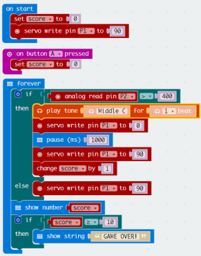
You might need to adjust the value of >400 based on your lighting conditions.
6. I use an old box to house my target game.
Making the gun
1. We will be using the laser pointer, battery case and micro switch.

2. Remove the batteries from the laser pointer and glue the laser pointer to the top of the battery casing. For my laser pointer, the spring (blue arrow) is -ve and the inner casing (orange arrow) is +ve. As the spring of the laser pointer is very difficult to access, I use a crocodile clip to clip on it.

| -ve of battery connected to crocodile clip. The crocodile clip is clipped on to the spring indicated by the blue arrow. | +ve of battery connected to micro switch. Another cable from micro switch to the inner casing of the laser pointer indicated by the orange arrow. |
3.Tie a cable tie around the switch of the laser pointer so that the switch remained depressed. Solder the micro switch and glue it to the battery case.
4. The outcome is shown below.


Compare six 4K USB cameras using IMX415, IMX274, and IMX678 sensors across resolution, color, field of view, distortion, Linux, and low-light tests.
REVIEWS
This article is an engineering test note, mainly intended to demonstrate the actual performance of the module in common development scenarios, rather than a laboratory calibration report.
REVIEWS
Visit DFRobot at FAB26 Boston for hands-on AI workshops, open-source hardware demos, and practical insights into K–12 maker education.
NEWS