EcoDuino Automatic Plant Waterer
This Article is created by The Soldering Station

EcoDuino is a kit from DFRobot for watering your plants automatically. It runs on 6 AA batteries that are not included in the kit. Setup is very easy and it includes an Arduino based microcontroller.
Step 1: Parts


You should have all of the parts shown here. Extras include two fun badges and 2 screwdrivers. We only needed the yellow screwdriver.
You should have the following parts: EcoDuino Control Board, battery pack, pump, moisture sensor, temperature/humidity sensor, plastic case (2 pieces), USB cable, 2 screwdrivers, 2 badges, 4 screws, and a plastic hose.
Not included are 6 AA batteries which you will also need.
Step 2: Verify Board Programming

We started by verifying we could connect our computer to the board and use the Arduino IDE to program it.
Plug the USB cable from the board to your computer and open the Arduino IDE. Select Leonardo as your board. If the board comes up in the board list, you are good to go. Disconnect the board from your computer.
Step 3: Sensor Test


Now attach the sensors. The sensors are attached vertically with the black or GND wire on the bottom. The humidity / temperature sensor goes in the middle slot and the soil moisture sensor goes above it on the side of the USB plug. Plug in both sensors and then attach the board back to your computer.
Copy the Sample Code and paste it into a blank Arduino sketch. Upload the sketch to the board and open the Serial Monitor to see the results. Download the DHT11 library, if you don't have it. Make sure to put it in your Arduino library folder. Put the soil sensor into the soil around a plant and see the values change on the serial monitor. See our orange elephant planter and fern plant. No elephants were harmed in the making of this kit.
Once this is working open a new blank file in Arduino and put in the Test The Pump sketch as we will do that next. Upload the sketch to the board. Now close the serial window and unplug the board from your computer.
Step 4: Pump Test


Now you need to wire up the pump. Connect the cable with the brown and blue wires shown in the photo to the pump cable.
Now connect the brown wire to the positive terminal and the blue wire to negative on the board labeled Solenoid Valve.
Now connect the other cable with red and black wires to the PWR terminal on the board. Connect red to positive and black to negative.
Load up the battery back with 6 AA batteries and connect the cable from the battery pack to the wire you just connected to the board. You should hear the pump go on and off. When this is working unplug the battery pack. Now that everything is working you need to put everything inside the case. Unplug the sensors from the board and unscrew and detach the cables you added.
*The pump needs 4.5 - 12 V and use .5 - 5.0 W of power. Not being sure what my computer's USB connection can handle, I never powered the board from the computer with the pump attached.
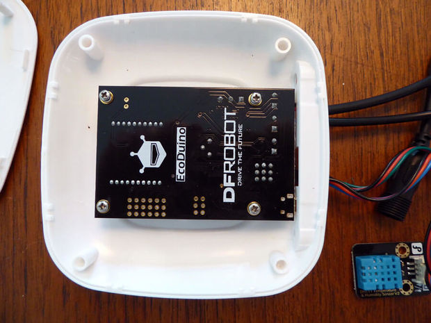
Step 5: Case Test Fit


Fit the board onto the plastic half with the holes in it. The board goes face down into the case. Line up the USB port with the port hole on the case. Also line up the four screw posts with the holes on the board. Also check board from the side with the holes so you can see where everything needs to go. When done take the board off the case.
Step 6: Case Fit

Thread the pump cable through rectangular hole and screw the wires back in to the connector labeled solenoid Valve. Connect the battery pack wires to the terminal labeled PWR.
Now push the sensor connectors through the hole on the plastic case in the middle and connect them to the board. Remember the humidity sensor goes in the middle and the black wire or GND goes on the bottom.
Now put the board back in place, lining up the screw holes with the plastic posts. Once the board is in place, go ahead and screw in the four screws to the plastic posts. Now attach the other side of the plastic case.
Step 7: Final Code
Now unplug the battery pack and pump by pulling apart the plug connections. Connect your board to your computer and paste the code Ecoduino Test into a new blank sketch in the Arduino IDE. This sketch combines everything such as reading the sensors and turning the pump on and off.
Currently the sketch is set to check the sensors every minute and water the plant for 1 second if soil moisture level is below 50. You can adjust these values in the sketch. Look for the 3 variables below near the top of the sketch.const long interval = 60000; // Change value to change time to check for watering. 60000 = 1 minute
int waterTime = 1000; // Change length of watering 1000 = 1 second
int moistureLevel = 50; // Adjust to know when to water
* 0 ~ 300 dry soil
* 300 ~ 700 humid soil
* 700 ~ 950 in water
You could add more code to make this better for the plant by checking the air humidity level. If the air moisture level is below a certain amount and the soil moisture level is low enough, then water the plant.
Upload the code to the board and unplug it from your computer.
Step 8: Final Setup

Now attach the clear plastic hose to the pump. Insert the pump into a small container of water. Stick the other end into a plant pot. Put the soil sensor into the soil around your plant and connect the battery cable and watch the water squirt out. How much water you get out also depends on where the plant pot is relative to the container of water. Put the water container under or below the plant pot for less water to come out.
Good job, that’s it, you are done!
For more tips and how to's, visit us at The Soldering Station.

Compare six 4K USB cameras using IMX415, IMX274, and IMX678 sensors across resolution, color, field of view, distortion, Linux, and low-light tests.
REVIEWS
This article is an engineering test note, mainly intended to demonstrate the actual performance of the module in common development scenarios, rather than a laboratory calibration report.
REVIEWS
Visit DFRobot at FAB26 Boston for hands-on AI workshops, open-source hardware demos, and practical insights into K–12 maker education.
NEWS