New: seeMote Cube for visionOS Developers - Build physical input for Apple Vision Pro apps. Learn More ›
ESP-WROOM-32 Tutorial: Uploading a program with Arduino IDE
The objective of this esp32 tutorial is to explain how to upload an Arduino program to the ESP-WROOM-32 module.
Introduction
The objective of this post is to explain how to upload an Arduino program to the ESP-WROOM-32 module, from DFRobot.
We will cover in more detail the hardware configuration needed to upload a program to the module. You can check in more detail how to enable the support for the ESP32 in the Arduino IDE on this previous post.
Please note that this is a ESP32 module suitable for integration in electronic designs and not a development board for testing/development. Thus, the pin spacing is very small and it requires some special manual soldering skills to be able to use it. Naturally, these kind of spacing is adequate for non-manual soldering procedures.
The hardware
In order to be able to upload programs to this module, we need a Serial-USB converter, so we can communicate with it. I’ve used the one shown here, which allows us to change between 3.3V and 5V operating voltage.
Important: The ESP32 is a 3.3V device and the WROOM module doesn’t do any voltage level conversion. So, the Serial-USB converter to be used must operate at 3.3V. Otherwise, the ESP32 may get damaged.
One thing that we need to take in consideration is that in order to be able to program the ESP32, the GPIO0 must be kept low [1]. Also, for the device to work, the EN pin (chip enable pin) must be connected to VCC, since it operates in an active-high configuration [2].
So, taking the previous points in consideration, figure 1 shows the minimal configuration needed to be able to program the ESP-WROOM-32 module. The other pins of the devices are not shown for simplicity. Also note that I’m assuming that the Serial-USB converter power is being supplied by the USB connection, which is the typical use case.
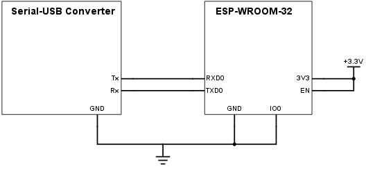
Figure 1 – Minimum hardware configuration needed to program the ESP-WROOM-32.
Please take in consideration that for the sake of simplicity I’m not following the best practices here, such as including power supply bypass capacitors and other important aspects needed to keep the device working with the best reliability. So please don’t use this hardware configuration in a final design, since it is only suitable for a quick interaction with the module.
Although in the figure we have the IO0 connected to GND, this configuration is only adequate for uploading the program. After that, you need to disconnect it from GND, so the program uploaded runs.
The code
The code for this tutorial will be very simple and consists in a simple “Hello World” message being printed periodically to the serial port. So, we start by opening a serial connection in the setup function, with a baud rate of 115200.
Next, on the main loop function, we will print a simple “Hello World” message. To do so we can call the println method on the Serial object. After that, we do a short delay by calling the Arduino delay function, which receives as input the number of milliseconds to wait.
Check bellow the full source code for this simple program.
void setup() {
Serial.begin(115200);
}
void loop() {
Serial.println("Hello from DFRobot ESP-WROOM-32");
delay(1000);
}
The Arduino IDE configuration
In order to be able to upload the code to the Arduino we need to select a suitable uploading configuration in the Tools menu. We can use the same configurations of the FireBeetle-ESP32 board, as shown in figure 2.

Figure 2 – ESP32 FireBeetle board selection in Arduino IDE.
After selecting this board and selecting the correct COM port assigned to the Serial-USB converter, just hit the upload button. The code should now be compiled and uploaded. After a correct upload, you should get an output similar to figure 3 on the IDE console.

Figure 3 – Message after successful upload.
After this, power off the module, disconnect the IO0 pin from GND and power the device on again. Then, open the serial monitor of the Arduino IDE. You should get an output similar to figure 4, where our defined “Hello World” message is being printed each second.
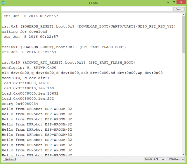
Figure 4 – Output of the “Hello World” program.
Additional notes
You can confirm if your soldering was correctly done before trying to upload your program. If you power on the module, connected to the Serial-USB converter and with IO0 disconnected from GND, a pre-loaded program should be running and printing the detected WiFi networks to the serial console, as shown in figure 5.
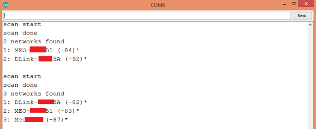
Figure 5 – Output of the pre-loaded program.
Also, if you power on the module with the IO0 connected to GND and the Arduino IDE serial monitor previously open, you should get an output similar to figure 6, which indicates that the ESP32 is ready for getting a new program.
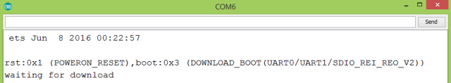
Figure 6 – Output of the module when in programming mode.
DFRobot supply lots of esp32 arduino tutorials and esp32 projects for makers to learn.

Compare six 4K USB cameras using IMX415, IMX274, and IMX678 sensors across resolution, color, field of view, distortion, Linux, and low-light tests.
REVIEWS
This article is an engineering test note, mainly intended to demonstrate the actual performance of the module in common development scenarios, rather than a laboratory calibration report.
REVIEWS
Visit DFRobot at FAB26 Boston for hands-on AI workshops, open-source hardware demos, and practical insights into K–12 maker education.
NEWS