New: seeMote Cube for visionOS Developers - Build physical input for Apple Vision Pro apps. Learn More ›
TUTORIALS ESP32ESP8266 The objective of this tutorial is to explain how to use the bitwise operators shift left and shift right. The tests on the ESP32 were performed using a DFRobot’s ESP32 module device integrated in a ESP32 development board. The tests on the ESP8266 were performed on a DFRobot’s ESP8266 development board.
ESP32 / ESP8266 Arduino: Bitwise shift operators
DFRobot
Apr 19 2018 263681
The objective of this tutorial is to explain how to use the bitwise operators shift left and shift right. The tests on the ESP32 were performed using a DFRobot’s ESP32 module device integrated in a ESP32 development board. The tests on the ESP8266 were performed on a DFRobot’s ESP8266 development board.
Introduction
The objective of this tutorial is to explain how to use the bitwise operators shift left and shift right. The code was tested on the Arduino core running on the ESP32 and the ESP866, but you should be able to use it in the Arduino environment on any board.
Note that the operators we are going to use are C/C++ operators, so most of the code we are going to develop here can be used outside the Arduino environment.
The notation for shifting left is shown below. It means that x will be shifted left by n bits.
x << n
When we shift left by n bits, we add n trailing bits with the value 0. So, if we shift left the number 00001100 by 2 bits, we get 00110000.
The notation for shifting right is similar and shown below. It means that we want to shift x right by n bits.
x >> n
In this case, if we shift 00001100 right by 2 bits, we get 00000011.
Note that there two interesting particularities of shifting right and left. Shifting left a binary number by one bit corresponds to multiplying it by 2. Shifting left by n bits corresponds to multiplying it by 2n.
Shift right is similar but it corresponds to a division instead. So shifting right by n bits corresponds to dividing it by 2n (integer division).
You can play with the shift operators in this web based tool.
The tests on the ESP32 were performed using a DFRobot’s ESP32 module device integrated in a ESP32 development board. The tests on the ESP8266 were performed on a DFRobot’s ESP8266 FireBeetle board.
The code
The code for this tutorial will be very simple, since we are just going to be printing some shifted numbers.
We will write all our code on the setup function. First, we will open a serial connection to output the results of our program.
Next we are going to declare an integer variable to which we are going to apply some shifts. We are going to use the value 10 as our base number, which corresponds to 00001010 in binary (represented as a byte).
int x = 10;
First, we are going to shift it right by one position. In binary, we should end with 00000101, which corresponds to 5 in decimal. This is coherent with what was explained in the introductory section, since shifting 10 right by one bit corresponds to dividing it by 2.
Serial.println(x>>1);
If we shift it right by two bits, we end up with 00000010. In decimal, this corresponds to 2. In this case, we shifted 10 by two bits, which corresponds to dividing it by 22. So, we obtain the quotient of the division of 10 by 4, which is 2.
Serial.println(x>>2);
Now we will do the shifts in the left direction. Starting with a shift of one bit, we obtain 00010100. In decimal, this corresponds to 20. This is because the one bit left shift on 10 corresponded to multiplying it by 2.
Serial.println(x<<1);
Finally, if we shift it left by two positions, we get 00101000, which corresponds to 40 in decimal. Again, this is because left shifting 10 by two bits corresponds to multiplying it by 4.
Serial.println(x<<2);
The final source code can be seen below. It includes some extra prints to help reading the results.
void setup() {
  Serial.begin(115200);

  int x = 10;

  Serial.print("x >> 1: ");
  Serial.println(x>>1);

  Serial.print("x >> 2: ");
  Serial.println(x>>2);

  Serial.print("x << 1: ");
  Serial.println(x<<1);

  Serial.print("x << 2: ");
  Serial.println(x<<2);

}

void loop() {}
Testing the code
To test the code, simply compile it and upload it with the Arduino IDE. Then, open the serial monitor. You should get an output similar to figure 1, which shows the results of our program. As can be seen, they are coherent with what we have been analyzing in the code section.
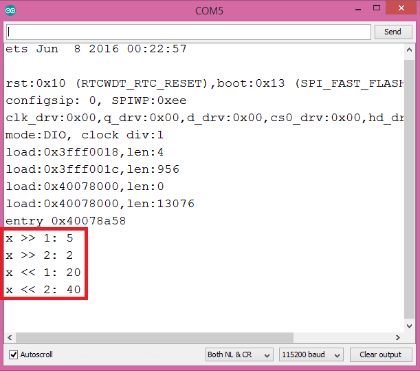
Figure 1 – Output of the program.
DFRobot supply lots of esp32 arduino tutorials and esp32 projects for makers to learn.
Recent Blogs

Hands-On Test of 6 New 4K USB Cameras: Resolution, Color, Field of View, and Compatibility
Compare six 4K USB cameras using IMX415, IMX274, and IMX678 sensors across resolution, color, field of view, distortion, Linux, and low-light tests.
REVIEWS Jul 23 2026

Fermion BMI323 6-Axis IMU Engineering Test Notes: Accelerometer, Gyroscope, Step Counter, and I2C Address Verification
This article is an engineering test note, mainly intended to demonstrate the actual performance of the module in common development scenarios, rather than a laboratory calibration report.
REVIEWS Jul 15 2026

Meet DFRobot at FAB26 Boston 2026: AI, Open-Source Hardware & Maker Education
Visit DFRobot at FAB26 Boston for hands-on AI workshops, open-source hardware demos, and practical insights into K–12 maker education.
NEWS Jul 15 2026