New: seeMote Cube for visionOS Developers - Build physical input for Apple Vision Pro apps. Learn More ›
TUTORIALS ESP32 Note that the code we are going to be developing here is based on the code available on the Wiki page of the product, which I encourage you to check.
ESP32 Arduino: Using an infrared CO2 sensor
DFRobot
Jun 11 2018 266362
Introduction
In this ESP32 tutorial, we will check how to get measurements from a C02 sensor, using the Arduino core.
The sensor used was an Analog Infrared CO2 Sensor from DFRobot. You can find the Wiki page for the sensor here.
Note that the code we are going to be developing here is based on the code available on the Wiki page of the product, which I encourage you to check.
The tests were performed using a DFRobot’s ESP32 module integrated in a ESP32 development board.
About the sensor
The Analog Infrared CO2 sensor allows to measure the CO2 air concentration in a range from 0 to 5000 ppm (parts per million), with an accuracy of ± 50ppm + 3% of the reading [1]. The sensor operation is based on the NDIR technology (nondispersive infrared) and includes temperature compensation.
This sensor can operate with a voltage supply in the range of 4.5 V and 5.5 V and outputs an analog signal between 0 V and 2 V [1].
If the analog voltage corresponds to 0 V, it means that an error was detected during the self checking procedure. Between 0 V and 0.4 V, it doesn’t represent any measurement and the values on this range are outputted during the pre-heating phase of the sensor, which has a duration of 3 minutes.
During normal operation, the sensor outputs a voltage between 0.4 V and 2 V, which corresponds to concentrations of C02 of 0 ppm and 5000 ppm, respectively. As can be seen in the product Wiki, there is a linear relation between the voltages in that range and the CO2 concentration, so we can obtain the concentration from the voltage using a simple proportion.
Electronic schematic
Since this is a ready to use module, the electronics needed for this tutorial are very simple. As illustrated in figure 1, we just need to power the device with 5 V and connect its data pin to a pin of the ESP32 that can read analog voltages.
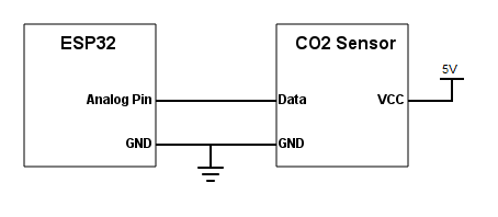
Figure 1 – Electronic schematic.
Note that the sensor doesn’t have any labels on the pins, so we need to perform the connections taking into account the colors of the wires that come with it. Following the usual color scheme, the black wire corresponds to GND and the red to VCC. The blue wire corresponds to the data signal.
Depending on your ESP32 board, it may be able to provide the power supply needed for the sensor from a power pin. Nonetheless, if you are not sure if it has such pin or if it can provide enough current to the sensor, the best approach is to use an external power supply such as this.
ESP32 Analog readings
As analyzed in the previous sections, the sensor outputs an analog voltage that the ESP32 will need to read. Since we are using the Arduino core, the easiest way of reading an analog voltage is by using the analogRead function, which is also implemented for the ESP32, as we can see here.
Nonetheless, at the time of writing, the analogRead function is returning inconsistent values on the ESP32, as can be seen by this issue. As discusses in this forum thread, this is most likely caused by the non linearity on the ADC (analog to digital converter) values.
You can check at the IDF documentation more information about this and some calibration methods that can be used.
Since these are more complex procedures that are outside the scope of this post, we will assume the linearity of the analog readings on the 0 V to 3.3 V range. Naturally, this will introduce some imprecision on out measurements, but the main focus of the tutorial is how to interact with the sensor rather than how to solve these non-linearity issues.
Since the ESP32 integrates two 12 bits ADCs [2], it means that we can obtain digital values between 0 and 4095 (212 – 1) for the analog voltage measurements. Note that we can change the bit width between 9 and 12 bits with the analogSetWidth function defined here, but for this tutorial we will work with the default value of 12 bits.
The code
For this code we will not need to include any library. So, we start by declaring the pin number of the ESP32 that will be connected to the sensor as a global variable, to make it easier to change in the future.
int analogPin = 35;
Moving on to the setup function, the only thing we need to do is opening a serial connection, to output the measurements.
void setup()
{
  Serial.begin(115200);
}
Now, on the Arduino main loop, we will handle the measurements, which will be performed periodically.
The first thing we need to do is obtaining the reading from the analog pin connected to the sensor. To do it, we simply call the analogRead function, passing as input the number of the pin we previously defined.
int adcVal = analogRead(analogPin);
As mentioned before, this will correspond to a value between 0 and 4095 (the ADC has 12 bits), which we will need to convert to a voltage. Assuming the linear behavior of the ADC, we can do this with a simple proportion, as can be seen below.
Note that we will obtain the voltage in Volts, which is why we store them in a float (to account for the decimal part).
float voltage = adcVal*(3.3/4095.0);
Now that we have calculated the voltage, we will handle the multiple cases that we can find. As mentioned before, if we get a voltage of 0 V, it means that some problem has occurred with the sensor.
If we get a voltage greater than 0 V but lesser than 0.4 V, then it means that the sensor is still on the pre-heating process. During this phase we still can’t get any measurement.
if(voltage == 0)
{
    Serial.println("A problem has occurred with the sensor.");
}
else if(voltage < 0.4)
{
    Serial.println("Pre-heating the sensor...");
}
else
{
    // Measurement handling code
}
In case we get a voltage equal or greater than 0.4 V then we need to convert it to a CO2 concentration value.
First, we need to subtract to the measured voltage the pre-heating threshold, since when the sensor is outputting 0.4 V it corresponds to a CO2 concentration of 0 ppm. Thus, we need to remove that offset from our measurement.
float voltageDiference=voltage-0.4;
Now, since the relation between the voltage measured and the CO2 concentration is linear, we simply need to apply another proportion.
float concentration=(voltageDiference*5000.0)/1.6;
After that we will print both the CO2 concentration obtained and the voltage measured. Note that we are printing the voltage just for illustration purposes and since we are using the print function without any additional parameters, this means that the floating point number will be printed with only two decimal places [3].
Serial.print("voltage:");
Serial.print(voltage);
Serial.println("V");

Serial.print(concentration);
Serial.println("ppm");
The final source code can be seen below. It includes a small 2 seconds delay between each measurement, to avoid constantly polling the sensor.
int analogPin = 35;

void setup()
{
  Serial.begin(115200);
}

void loop()
{
  int adcVal = analogRead(analogPin);
  float voltage = adcVal*(3.3/4095.0);

  if(voltage == 0)
  {
    Serial.println("A problem has occurred with the sensor.");
  }
  else if(voltage < 0.4)
  {
    Serial.println("Pre-heating the sensor...");
  }
  else
  {

    float voltageDiference=voltage-0.4;
    float concentration=(voltageDiference*5000.0)/1.6;

    Serial.print("voltage:");
    Serial.print(voltage);
    Serial.println("V");

    Serial.print(concentration);
    Serial.println("quot;ppm");
  }

  delay(2000);

}
Testing the code
To test the code, simply compile it and upload it to your ESP32 device after performing all the electronic wiring needed.
If you did not power your CO2 sensor beforehand and waited for the pre-heating time, then you should start obtaining the pre-heating message we defined on the code, as illustrated on figure 2.
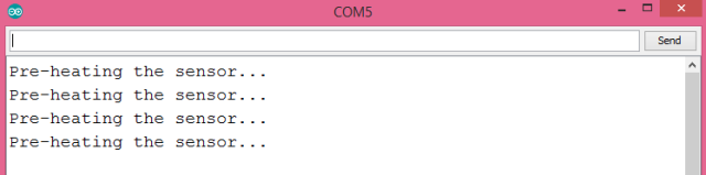
Figure 2 – Pre-heating phase.After the pre-heating phase, you should start obtaining measurements, as illustrated in figure 3. The measurements shown here were taken inside a closed room. If you check here, they are near the end of the interval expected for indoor spaces.
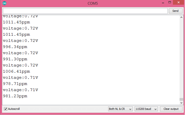
Figure 3 – Measurements taken on a closed room.
On figure 4 we can check some measurements taken near a very big opened window. As can be seen, the concentration of CO2 measured reduces considerably.
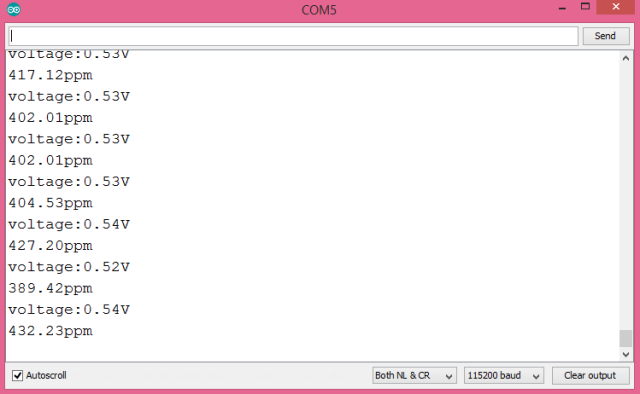
Figure 4 – Measurements taken near an opened window.As mentioned before, since we are assuming a linear behavior for the ESP32 ADC and since the non-linearity is not corrected in the APIs, the measured values are not very accurate and can be improved. So, this tutorial illustrates how we can interact with the sensor and how it behaves, but you should not use the code without correcting the ADC measurements if you need accurate readings of the CO2 concentration.
Recent Blogs

Hands-On Test of 6 New 4K USB Cameras: Resolution, Color, Field of View, and Compatibility
Compare six 4K USB cameras using IMX415, IMX274, and IMX678 sensors across resolution, color, field of view, distortion, Linux, and low-light tests.
REVIEWS Jul 23 2026

Fermion BMI323 6-Axis IMU Engineering Test Notes: Accelerometer, Gyroscope, Step Counter, and I2C Address Verification
This article is an engineering test note, mainly intended to demonstrate the actual performance of the module in common development scenarios, rather than a laboratory calibration report.
REVIEWS Jul 15 2026

Meet DFRobot at FAB26 Boston 2026: AI, Open-Source Hardware & Maker Education
Visit DFRobot at FAB26 Boston for hands-on AI workshops, open-source hardware demos, and practical insights into K–12 maker education.
NEWS Jul 15 2026