New: seeMote Cube for visionOS Developers - Build physical input for Apple Vision Pro apps. Learn More ›
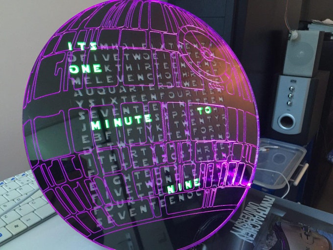
Death Star word clock
This project is made by Jordy Moors and originally published on hackster.io.
THINGS USED IN THIS PROJECT
Hardware components:
Particle Photon × 1
neopixel × 1
32x32 RGB LED matrix 6mm pitch × 1
RGB matrix shield × 1
Software apps and online services:
Hand tools and fabrication machines:
Laser cutter (generic)
Soldering iron (generic)
Background
"So you made a clock huh?" - Yes, I made a clock, a cool one though.
When I was little, my mom held back on teaching me how to read a regular analog clock so she could send me to bed earlier when she saw I was tired. Smart move. Unfortunately, analog clocks have since never been a great joy in my life, so I set out to look for something different. I've been used to using digital clocks, but they got boring too after a while. That's around the time I saw a word clock for the first time. "That makes so much sense" is one of the first things I thought, and the seed was planted.
Fast forward to Maker Faire 2015, where I had the pleasure of meeting the Particle team and several of the Elites, I noticed one of the latter was building a word clock as well. That's what gave me the final motivation to build one myself. Luckily I saw him struggling with soldering well over a 100 Neopixels for over a day, and I decided mine would have to be simpler. One of the other Elites had made an interesting project with an RGB matrix, which sparked the idea that those two might make a great combo.
Fast forward a bit more, and I started contemplating about how to best build my own version. I knew I wanted it to be something 'different', and a bit more 'advanced' than those 5-minute-accurate versions. There's nothing wrong with those, but I wanted more. Having always been a fan of Star Wars I thought it'd be fun to somehow combine those. Unknown to me at the time was that this contest was coming up, which was a welcome incentive to actually start doing something, rather than just dreaming about it.
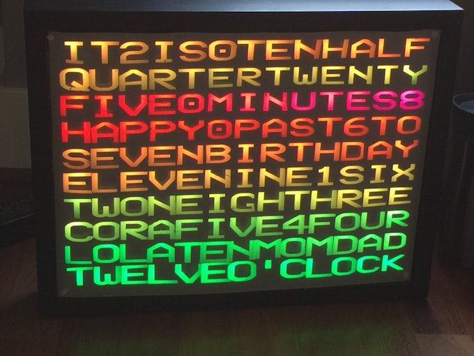
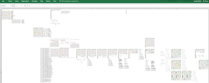
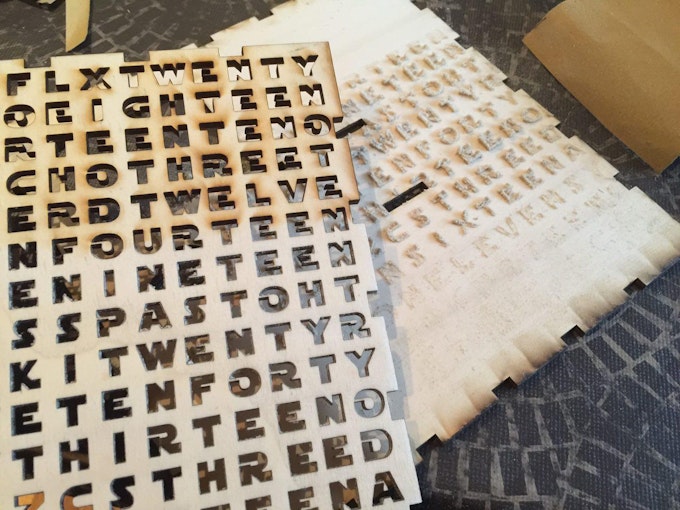
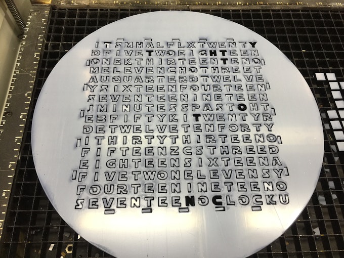
Lettering design
So, a word clock apparently needed words. I know, who would've thought, right? Hopeful as I was, I thought some smart person had probably figured out an algorithm to figure out the patterns. I found exactly one program, run in some Java machine that could do some basic layouts. First problem was the fact that I couldn't for the life of me get it running. Second problem was that it was relatively 'basic'. It could only do horizontal words, and only specific sets. Either was a no-go since I wanted vertical words as well as double sets.
After abandoning all hope of finding an existing layout (that's what you get for wanting custom things), I figured I might as well pull out trusty old excel and start puzzling. After about three days of frustrations, I managed to cram in as many Star Wars references as I could while maintaining the word clock functionality. Lovely.
Now, in this layout I opted for a 'double system', so that you could display the time in the most common ways. The first being "It's MM minutes past/to HH", and the second one being "It's HH (o) MM". "Why would you want that?", I hear you say, well, because I could. No particular reason other than me thinking it was a good idea.
The reason it was so difficult to design this was because I wanted not only horizontal words, but vertical ones as well. With horizontal ones only, I would've probably had 2 rows left over. Unfortunately, things become quite a bit more complicated when they need to line up for the several words I wanted hidden in there. That also means that if you take those word out, there's quite a bit of space left for alternatives, such as weather conditions.
Case design
For the case I had several ideas. I thought of making it a BB-8 with a rotating head. It'd be in 2D, and the head would be able to rotate around the body. Alternatively, I though of making a Death Star with a laser beam out of fiber, like this guy did. Finally I figured edge-lit acrylic might look really neat as well. Seeing as the construction of a movable BB-8 was outside the reach of my capabilities, and there was no good way to combine the fiber with the matrix, I opted to go for the edge-lit acrylic.
The casing itself I wasn't too sure about, and hadn't really put too much thought into it either. The day before I could use the laser cutter at the FabLab at my school, I put together a simple box design. I got some 4mm plywood, and cut my casing out of it.
All design work has been done in both AutoDesk and Adobe Illustrator. I had used neither of these tools before, so it was mainly drawing lines by hand. It's a good way to get to know the software, so I'd recommend it regardless.
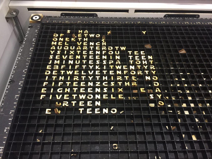
Building the casing
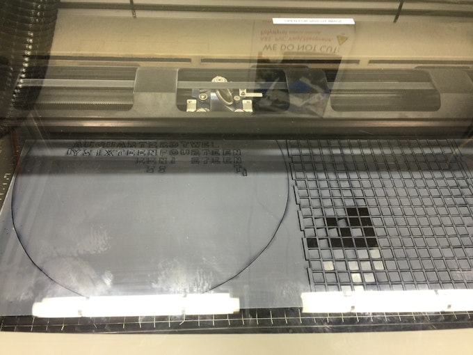
It was decided that the front plate would be clear acrylic lasered with a Death Star pattern that was to be edge-lit with a bunch of neopixels. The casing would be 4mm ply. To defuse the light, slightly opaque acrylic would be sandwiched between the front plate and the letters. So, that's what I did. I went to the FabLab, and lasered everything. Much to my surprise everything fit from the first go-around.
Pros:
- Clear acrylic looked REALLY NICE when lit.
- Opaque acrylic gave a holographic appearance with a single LED.
- Plywood was cheap.
Cons:
- Opaque acrylic diffused too much, made it hard to read.
- Ply didn't look as nice unpainted.
- Ply didn't look nice at all painted due to the wood; looked like smudges.
- No idea how to attach the front plate.
- My matrix kept falling backwards due to lack of support.
Solution:
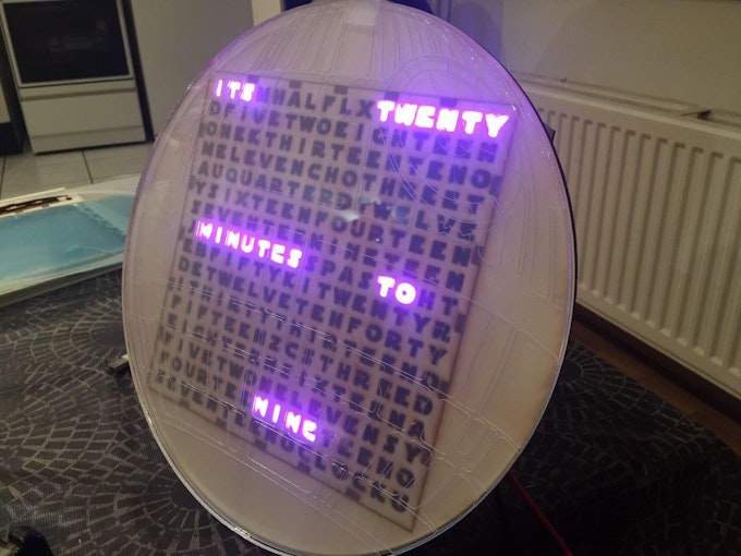
Build a new casing, using 3mm black acrylic. It's shiny, and looks really really nice. It has that "professional product" look to it. It didn't come cheap since I needed it desperately and couldn't find it anywhere else. Worth it in the end. Looks much more professional and finished, and with a bit of electrical tape was very easy to neatly attach to the front plate. I also added internal supports for the matrix, so that stays in place very well now. Putting it together can only happen in one way, and that's pretty self-explanatory. Looks so much better now:

The electronics
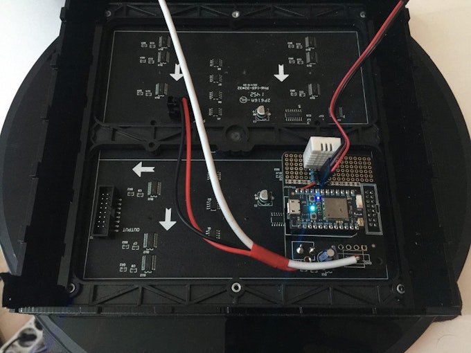
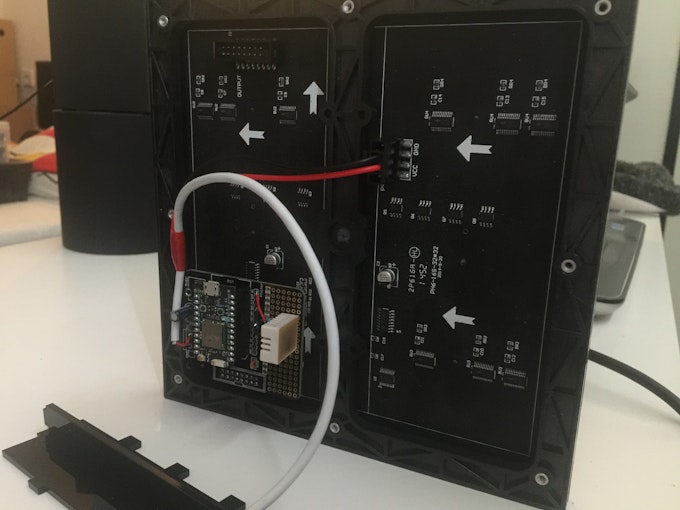
Although it might look like a complicated project it was actually very easy to do. The matrix made life a whole lot easier by now having to solder all those LEDs manually. So worth it. Hooking up the Photon to the Matrix was a breeze since @Peekay123 had so kindly provided me with one of this RGB Matrix shields. You plug the Photon in the shield, and the shield in the matrix, and that's it. Soldering the components to the board was all that was needed (which are about 20 pins).
The prototype area on the shield came to good use for hooking up the Neopixel for lighting the acrylic. At first I planned on putting a strip around the whole thing, but a single LED was bright enough that that wasn't necessary anymore. So, with another three wires, the neopixel was hooked up, still very easy to do.
Sound
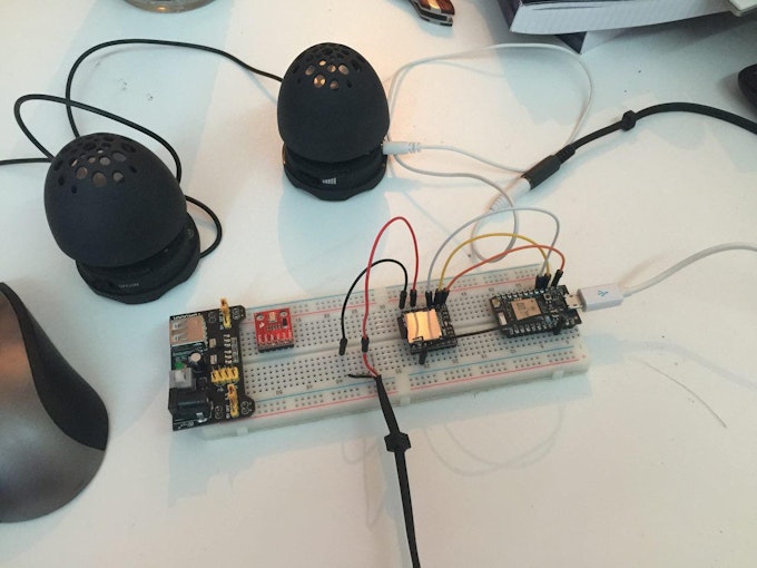
I figured it'd be cool if the clock could play sounds of some sort so it could be used for notifications, or just for fun. To that end I bought some cheapish music module from Ebay. Unfortunately I couldn't get the thing working and had to abandon the idea. In that same time, there was a post on the Particle community about a "cheap MP3 shield", which seemed interesting. I thought I could always add it after the contest, so I ordered two.
Much to my surprise, they arrived after 6(!) days from China - Netherlands. Totally unexpected, I had made no preparations to include it anymore. Still wanting to try it, I set it up on a breadboard with another Photon, and used the power of The Force (Internet) to connect the two. Using Particle publish and subscribe made this surprisingly easy to do. This is unfortunately not yet encased due to an exam messing up my time, but will be in the future. For now, it can be hooked up to pretty much any headphone jack. I've used two small speakers to test it, and it works wonderfully.
Power
Powering the clock was/is a challenge. The Matrix can draw up to 4A when fully lit, and the photon about 300mA. One single neopixel can also draw 60mA. All those combined made it tough to power. The shield included a barrel jack and a 4 pin or screw terminal to connect to. Unfortunately I didn't have a beefy enough 5V supply laying around, so I decided to cheap-skate a little bit. (The following is how I did it for now, this will be fixed in the future and is by no means permanent, nor should it be!) I soldered an old USB cable to the shield and hooked that up to an iPad charger. Now, those only provide 2.1A, so are clearly not enough when you go all-out. Luckily, most of the time most of the pixels are off. You only need a couple to display the time, so you end up with a lower requirement. Admittedly, it's not good to design your system based on those assumptions, so I'd wholeheartedly recommend you get a decent power supply.
Software
Hardware can't do a thing without software, and that's where the 'magic' happens. Like I mentioned before, I wanted something 'more' than just a 'normal' word clock. I wanted something cool. I ended up putting different modes on it which you can use. Let's go through them briefly.
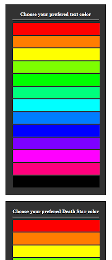
- Word clock: This is the word clock as you know it. It tells time and does so in one of two syntaxes. You've got "It's MM minutes past/to HH" and "It's HH (o) MM" to choose from. You can change the colors of the text as you please, and it should be fairly straightforward to extend this to full rainbow colors, for those interested.
- Matrix animation: This is the 'digital rain' from the matrix movies. What better medium to play it on than a matrix with letters. Match made in heaven (or code, actually...) For this part I used code from Carbon Frog who also design word clocks. I'm no lawyer, but I understood the code was free to use according to the license. I had to edit very minor parts to make it line up with the code I already had in place, and account for the difference in size. Other than that, it wasn't too hard. All credits to them for that code, I merely merged that. (I don't wish to infringe on anything, they've got nice code, and I was glad I could use it. Check them out, they make nice things!)
- Digital display: Use the matrix as a matrix and display the time in a digital fashion. Use the individual letters as pixels to make up digital letters. Easy to read from further away due to the increased size. Ideal for those mornings where your eyes are still stuck to your face.
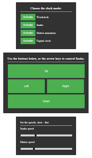
- Snake: this might not be Star Wars related, but it's still really cool. As the name suggests, you can play Snake. Controls are currently through a web browser, but could just as easily be capacitive touch, movement sensors, accelerometers, and all kinds of crazy stuff. There are some Star Wars elements in it though, check the videos at the bottom for those.
Besides those modes, there are also the 'hidden' words that can be activated on demand. I won't spoil them, but can say there are 6 things to find in there, for those interested in searching. Linking this up with the sounds makes for a very neat effect. You see the clock display its gimmick, and hear speaker somewhere else accompany it. If that isn't IoT Force power, then I don't know what it ;).
Alternatively, this could also be used in a more useful fashion. IFTTT for example allows you to connect a huge amount of online services to it. Making LEDs blink, playing sounds, showing messages, and things like that are all very easy to do thanks to services like this. Tagged in a photo on facebook, blink blue. Got an email on gmail, fade red. This could even act as a notification devices for people with disabilities. It's both a graphical and audio stimulant that can warn them of certain events.
The code itself is not too difficult to understand, and should be fairly self-explanatory. Should you encounter anything that's hard to understand, feel free to ask, and I'll try my best to elaborate!
Interaction
Currently the Clock is controlled by a web page. It's made with the Particle Javascript library, and it kept as basic as possible to allow for easy customization. It too, should be rather easy to understand, since most actual actions are function calls to the clock, everything else is mostly cosmetics. Again, if something is unclear, feel free to ask!
In the future I'd like to expand the interaction possibilities with capacitive touch sensors. Those can be placed on the backside but can be triggered from the front. Not only does this look really neat and Star Wars-ish, but it also allows for local control, which despite the IoT era can still be nice every once in a while.
As mentioned before, services like IFTTT allow for very easy connections between online services. With Particle being one of said services, there's a lot of combinations to make, depending on your needs, wants, and or interests. Some like facebook notifications, other the current stockprice. Both are possible.
It also serves as a geeky communication device if you want it to. By using the matrix capabilities, it's possible to scroll text on the screen. Combining that with an active internet connection, and you've got a very simply and fun way to send messages to loved ones. Hook it up to IFTTT and you can even text it, or tweet it, or...
Display environmental data; those with a keen eye have probably noticed the extra sensor on the shield, that has been left unmentioned. That was in fact a DHT22 temperature and humidity sensor. Due to exams I have not been able to integrate this yet, but it's very doable, and shouldn't be too hard. That'll allow you to use the clock as an indoor thermostat. With the power of the internet you could also pull down weather data, and set it up as a local weather station, notifying you when it's going to rain and/or when it's going to be really hot.
I could go on like this for a while, but it should be obvious by now that there is no lack of possibilities.
Build your own
So, for people interested in building their own, I'll try and lay out the steps you might take to get this going. First of all, make sure you've got a bit of time to spend on this. Depending on what materials and equipment are available to you, not to mention your skills, this could take a weekend. Well spend, if I may say so myself.
Design
Download the design files, and load them up in your favorite editor. Make sure everything still has the proper dimensions, since importing files can often mess with this. The design I've uploaded has been made to work with 3mm material for the entire casing. The front plate should be 5mm clear acrylic for the best effect, since it's the same thickness as a neopixel. Then, find a place where you can use a laser cutter if you haven't got one yourself. See what type of files they require for their cutter and make sure you convert them to the appropriate format before going there. There's nothing worse than getting there with all the materials only to find out your files won't work. Time is precious, and cutting the whole clock took around 1.5 hours on a 35W Epilog Zing laser cutter. Depending on what device you have access to, that time may vary.
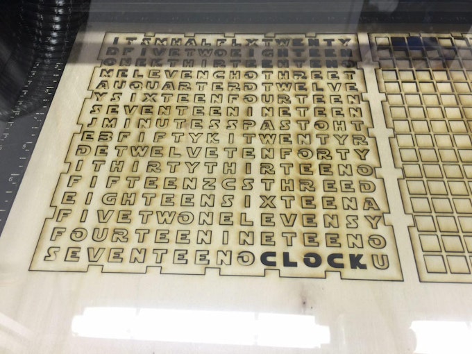
Cutting the materials
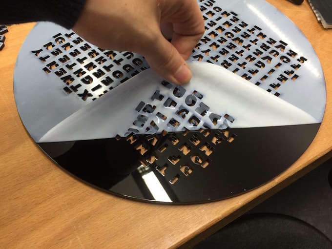
Once you've made sure all your files are okay to go for the machine you'll be using it's time to gather materials (if you haven't yet some so). Personally, I started with a 4mm ply case, but switched to 3mm black acrylic since it doesn't require finishing. You peel off the protective plastic and it looks amazing, whereas you'd have to sand the wood, paint it, and then hope it turns out right (which it didn't for me). Again, make sure the thickness matches the design and visa versa! Then, for the front plate, get clear 5mm acryllic, at least 30 by 30 cm (the plate itself will be 29cm diameter). Once you've got all that, go to your favorite laser cutter, prime it according to the specifications, load the materials and hit 'go'. Then, continue to watch in awe as you're making a PEW PEW laser WoMD by using a PEW PEW laser. Neat, isn't it?
Electronics
Right, as I've mentioned, it was a rather easy project in terms of electronics, since I had this neat little shield. I'd highly recommend you to get one as well, since it make the process a whole lot smoother. Alternatively, you can design your own, of even use a protoboard if you like. The former gives a lot of flexibility in terms of design, allowing you to change things as you please (bigger smaller proto area for example). The latter option is probably one of the cheaper ones, although you'd have to solder all connections yourself, which can get rather messy. Again, the shield is a worthwhile investment, if only to save you the hassle of soldering the connections, while allowing for plug & play functionality.
Regardless of what option you choose, you'll need to solder the shield, and the neopixel to it. In the attachment is a schematic of how the neopixel should be connected. Due to a lacking part for the shield, I've used a 'bare' neopixel on a 'bare' Photon. Luckily, the pins are marked on the shield as well, so it should be rather trivial to solder them. I chose to use male headers on the board, and female Dupont cables for the neopixel, you I could easily take it off for servicing. You can solder them permanently as well, though you'll have to be a bit more carefully when dis(assembling).
Assembly
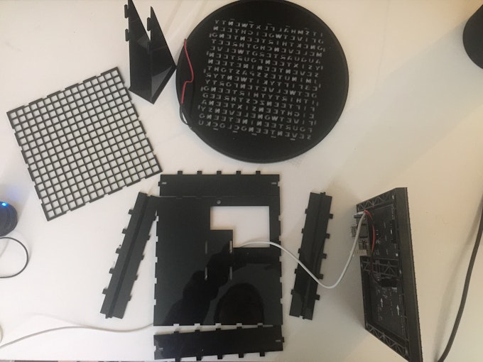
Once you've got the parts and electronics ready, it's time to assemble. It's rather self explanatory, but let's go through it regardless. The pictures below might help, but let's talk through it as well.
I'd suggest laying out the pieces so you've got a nice overview of what you've got. Put the backplate down, with the hole on the top right side. Put the four sides on their respective sides, making sure you mirror the pieces. Then, put the small supports in the two sides. These too need to be mirrored, since the holes need to align with the small 'pins' on the matrix. With a bit of fumbling, raise the sides up, and interlock them using the holes.
Once that's done, I'd suggest putting a little bit of scotch tape on the sides an back to keep it together temporarily. Continuing, you should now be able to lay in the matrix, which should sit flush to the case. Make sure you properly align it, since the shield should be able to go through the hole in the back. All good, moving on, put the raster over the matrix, which should prevent the light from 'bleeding' into the other letters. Then, to diffuse the light (the matrix is awfully bright), cut a piece of paper to 192mm by 192mm, and put that over the raster. Finally, add the letter plate by pushing it onto the sides. Just so I've said it, make sure you align it properly. With the bottom hole in the top right, the text should be readable from top, left to right.
Attaching the LED and front plate will be done simultaneously. Make sure both the Letter plate and the front plate are as clean as possible. You don't want to remove them after this. Put the front plate on the letter plate, making sure the 'laser nozzle' lines up with the 'E' in the top right corner. Then, using black electrical tape, start taping the two sides together, making sure the top of the tape is flush with the top of the plates. Gently turn the clock as you attach the tape, and press is gently to make sure it sticks. Due to the stretchiness of the tape, it curved nicely around the back, thus eliminating the need to cut it. Just before you reach full circle, cut if off, leaving about 5 mm of acrylic exposed, since that's where your neopixel is going to go. Prior to attaching the neopixel, I suggest coloring the sides black with a sharpie, since you'll then not notice it as much. Once that's done, put the neopixel against the clock, and stick a small piece of electrical tape over it to secure it.
Turn the clock over, and plug in the shield. If you hadn't yet attached power cables to your Matrix, you can remove the backplate, and do so now. Put the backplate on again, and insert the feet. You should be able to put them through the holes, and slide them up. If you want to hang the clock to the wall, you can omit the latter step, and use the small hole on the top to hang it.
Depending on the materials used and the accuracy of the laser cutter, things might somewhat loose, or somewhat tight. If you're lucky, the clock will hold with pressure fit, eliminating the need for adhesives. If it's on the loose side, you can consider using the black tape again, of perhaps some specialized acrylic glue. Since mine seems to hold up just fine, I've used neither.
That's it, mechanical and electrical construction completed.
Code
unfortunately, smart robots are (still) a Star Wars dream, so unless you tell it what to do, it's not (yet) going to think for itself. To that extend, we need to put some code on it. Considering the fact that Particle is really awesome, the shield was made for it, the fact that I had every intention of using one, and this contest requires one, I figured I might as well use a Particle device for that ;) I suggest you do the same.
Okay, so you've got your Photon, and you've set it up. Assuming you've had no trouble doing so, you should have a cyan breathing device, which you can toggle the D7 led with using the app. If something did go awry, or you encountered issues, consider checking out the community for help. There are some very lovely folks on there, who'll gladly lend a hand.
So, with a working Photon, go to the web IDE. There, create a new app, and give the poor thing a name. Once that's done, use the libraries system to manually include the following libraries: neopixel, SparkIntervalTimer, Adafruit_mfGFX, RGBmatrixPanel. You have to do these manually, the IDE won't select them otherwise. Continuing, click the little '+' icon in the top of the idea to create a new tab (in the IDE, not your browser). Name the new tabs 'snake' (case sensitive!). Once that's done, copy the contents of the respective attached files into the tabs on the IDE. Finally, copy the contents of the main file, and paste it over whatever is in the main app on the web IDE by now. Make sure you edit the 'timezone' variable at around line 85-95 to make sure it matches the one you're in. After selecting the correct device and saying a little prayer, hit the 'verify' button, and hope everything works out the way it should. For those who don't know, that's when it says 'ready!' and doesn't give you a bunch of errors. If it works, hit 'flash' and be amazed at how you're now flashing a micro controller wirelessly, thanks to The Force (and some really, really awesome people over at Particle HQ!).
If all went well, your Photon should now restart, and your clock should come to life. Isn't that awesome?! (Yes! Yes it is!) Now, casually whisper (scream): "POWER! UNLIMITED POWER!", and gloat while your loved ones stare at you as if you've finally gone completely mental. Totally worth it though!
Control
The clock will actually run just fine on its own, but the real fun comes in the you can make it do stuff. For that I've made a really simple web page that'll allow you to control the clock remotely. To use it, place the three web related files (.html, .css, and .js) in the same directory. Then, edit the .html file with a text editor to replace your credentials in the appropriate places. They should be your Particle account email/password as well as the deviceID from the Photon you've used. The latter can be found be clicking the little arrow next to the device name in the Web IDE. If completed, open the .html file in your browser, and click away. If nothing got messed up, you should now be able to control your clock. If you manage to get these files on a web server, this will work from anywhere in the world. Controls, done.
With the clock and controls finished, the project it pretty much done. Although, it'd be really cool and convenient to add some sounds to it as well...
Sound
As mentioned, due to conflicting timetables (exams) and bad modules, I wasn't able to integrate sound into the casing before the end of the contest anymore. What I was able to do, was hooping up a good module to a separate Photon, and trigger that using the Force (Particle.publish and subcribe). That allowed me to quickly and easily test the setup without having to solder it in yet. As a matter of fact, I might leave it separated as is, since I can now place the clock and the sound in different places, making for a cool effect. The 'sound' Photon could even be used to add some physical controls to the clock as well.
To integrate sound, hook up the DFMini MP3 player as depicted in the attached schematic. Then, put some MP3 files on an microSD card, and be sure to name them XXXX_whatever. The XXXX would be the number of the song. "0008_Empire" for example would be the eight song. Insert the card, and make sure you've got some speakers hooked up.
Using the same procedure as before, create a new app in the Web IDE and copy the attached code into the project. This one doesn't use any libraries, so you don't have to worry about that. Flash it to the device, and wait for the Photon to restart.
If everything went according to plan, the clock should now trigger various sounds upon certain actions. Give Snake a try, of try activating some of the hidden words through the control page.
For those who can't wait to see it, here it is in its full glory. The breadboard on the left is in no way connected to the clock besides through the internet. All interactions happen through the Force (and satellites, servers, transatlantic cables, fibre, ISPs... mostly The Force though).
Well, in all honesty, what good would a Death Star do if you can't fire it? Remember that 'E' you had to align the nozzle to, well, here it is...
Now, let the apprentice become the master. I've trained you well, young Padawan, time to explore the galaxy on your own. Go forth, and expand upon what I have given thee. Build a clock, you must!
Conclusion
I've built a clock. And it's a pretty neat one. Mentioned several times, I wanted to create something 'more'. Designing a one-off 'ultimate' Star Wars project would've been cool, but then it would've been just that: 'ultimate Star Wars'. Instead, I (think) I built something that's not only ecstatically pleasing (I got my mom' seal of approval for a glowing Death Star, that's enough evidence for me...), but that's also actually useful. Yes, "it's just a clock", but I'll bet you I'll use a clock more often than a light saber (unfortunately...). With this project I've made something that's not only nice to have for now, and when my geeky friends come over, but it's actually something anybody could enjoy, due to the 'extreme' customization options. Swap the Death Star for your favorite Instagram quote, and you've finally got an excuse to use it. Hook up some IR LEDs and control your appliances. Use it to let your loved ones know you're thinking about them. Enable people with disabilities to have other means of notifications. Or, you know, attach a laser and blow up some planets. There's something for everybody.
Alternatively, just enjoy the beautiful thing you've just made :)!
Much more fun with sound, though still not as easy ;)
A final word of thanks to all the people who made this possible. The Star Wars universe is what inspired this. Several other people made it a reality, for which I'm grateful. With that said, all rights go to their respective owners, and I do not want to take credit for what isn't mine. I've tried to give credit where it was due, but for the ones I might have forgotten, there's this: thank you! No infringement of any kind is intended. The contents I've used, has been used because I very much admire the things you've created, and I hope you can see it as such. I tried my best to combine all the components into the project that it has become, and I think it turned out rather nice.
"Remember...the Force will be with you, always."
CUSTOM PARTS AND ENCLOSURES
CODE Download
CREDITS
Jordy Moors
Student at the RWTH Aachen, Germany. Studying EE and computer science. Like technology (doh...)
More Particle Photon Projects:
- Particle Photon Project 1: IOT Plant Moisture Notifier
- Particle Photon Project 2: E-Paper Weather Display With Photon and IFTTT
- Particle Photon Project 3: Annoying Soil Moisture Sensor with Photon and IFTTT Project
- Particle Photon Project 4: Death Star word clock
- Particle Photon Project 5: How to Make a Makerspace NFC Part Management System

Compare six 4K USB cameras using IMX415, IMX274, and IMX678 sensors across resolution, color, field of view, distortion, Linux, and low-light tests.
REVIEWS
This article is an engineering test note, mainly intended to demonstrate the actual performance of the module in common development scenarios, rather than a laboratory calibration report.
REVIEWS
Visit DFRobot at FAB26 Boston for hands-on AI workshops, open-source hardware demos, and practical insights into K–12 maker education.
NEWS