New: seeMote Cube for visionOS Developers - Build physical input for Apple Vision Pro apps. Learn More ›
PROJECTS Robotics
(1)Chassis diameter: set Robot Diameter as 0.36 meter, the actual diameter of chassis (circumcircle).
Lesson 2 - How To Build An Automatic Navigation Robot (Based On The HCR Robotic Platform)
DFRobot
May 16 2017 261750
In the last week, we finished hardware configuration:
How To Build An Automatic Navigation Robot ( Based On The HCR Robotic Platform) : Lesson 1
Today we will complete firmware code configuration!
Components:
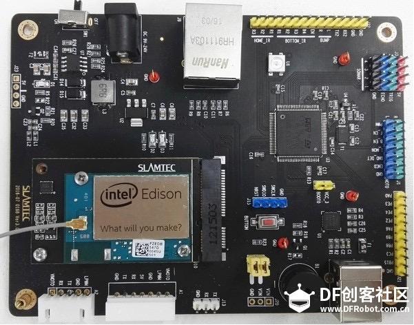
(1)Slamware breakout V3.0
(2)RPLIDAR A2 - 360 Degree Laser Scanner Development Kit

(3)HCR - Mobile Robot Platform with Sensors and Microcontroller

(4) Ultrasonic sensor*3
(5) Motor drive
(6) High current lithium polymer battery
(7)DuPont lines, a VCC, GND expansion panel (homemade)
4. STM32 Firmware configuration
Chassis firmware code needs to be modified to the specific parameters suiting the current chassis. You can use slamware_config_tool.exe tool to automatically generate configuration file:
Configuration tool link: http://pan.baidu.com/s/1qXHWDzQ Password: 3hs6
Open slamware_config_tool.exe and add the following parameters:
(1)Chassis diameter: set Robot Diameter as 0.36 meter, the actual diameter of chassis (circumcircle).
(2)Position setting of ultrasonic and collision sensors: set the coordinates (x, y, z) and angles (counterclockwise) of 3 ultrasonic sensors and 3 collision sensors. Coordinates are shown below (origin is the center of platform):


(3) Lidar settings: in the following sheet, coordinates (x, y) are the mounting position of radar center under the said coordinate system. Angle is 0 degree along the advancing direction opposite to interface lead, interface lead forward 180 degrees as the experiment is lead forward. Parameter settings need to be converted into radian system


(4)Motion Plan and Feature configuration
Motion Plan applies default configuration

Remove Has IR Tower on Feature page

After completing configurations of all parameters, click Export at the upper right corner, save the configuration file as binary_config.c, and put it in the source code of project.
Code modification:
(1) Replace binary config.c file in Source of project.
(2) Adjust PID parameters and pulses per meter of motor
a. PID control algorithm parameter debugging method
Gradually increase P value and I value from 0, until the robot could respond quickly and doesn’t start quivering. Reference value of the experimental platform is P=1, I =0.2, D=0. You can also independently set PID parameters of motor.c to achieve the desired effect.

b. Calculation of pulses per meter
The motor could output 663 pulse feedback signals per rotation. Wheel diameter is 13CM. We can calculate that one meter is equivalent to 2.45 rotations. Therefore, pulses per meter is 663 * 2.45 = 1624 (set in motor.h)

5.Firmware burning
We can short-circuit BOOT0. Connect the serial port shown below on breakout. Use flyMcu tool to burn the adjusted firmware to MCU. On-line operation is shown below. After completing burning, restore pin connection


Download link of flyMcu tool
Link: http://pan.baidu.com/s/1o8MuF0I Password: 717j
Related Product

Recent Blogs

Hands-On Test of 6 New 4K USB Cameras: Resolution, Color, Field of View, and Compatibility
Compare six 4K USB cameras using IMX415, IMX274, and IMX678 sensors across resolution, color, field of view, distortion, Linux, and low-light tests.
REVIEWS Jul 23 2026

Fermion BMI323 6-Axis IMU Engineering Test Notes: Accelerometer, Gyroscope, Step Counter, and I2C Address Verification
This article is an engineering test note, mainly intended to demonstrate the actual performance of the module in common development scenarios, rather than a laboratory calibration report.
REVIEWS Jul 15 2026

Meet DFRobot at FAB26 Boston 2026: AI, Open-Source Hardware & Maker Education
Visit DFRobot at FAB26 Boston for hands-on AI workshops, open-source hardware demos, and practical insights into K–12 maker education.
NEWS Jul 15 2026