New: seeMote Cube for visionOS Developers - Build physical input for Apple Vision Pro apps. Learn More ›
PROJECTS OBLOQIoTGravitySolar
Motivation:
Functional design:
Components List:
Product making:
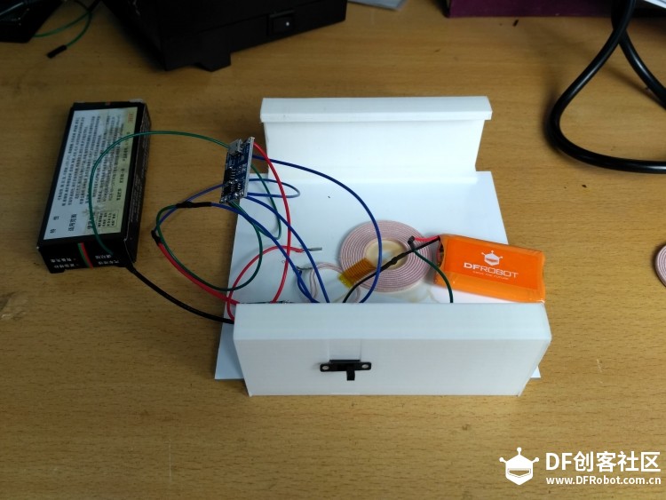
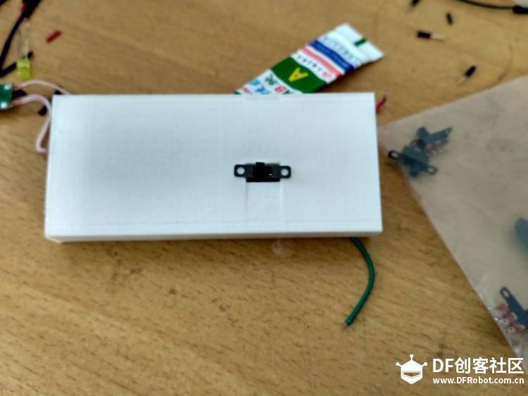
In addition, we also added a switch in the lithium battery circuit for controlling the on/off of energy.
Wireless Power Supply Smart Road Based on IoT Platform
DFRobot
Apr 10 2018 261506
Motivation:
Under the pressure of energy and environmental protection, new energy vehicle will undoubtedly become the vehicle development direction in the future nowadays. However, new energy vehicle faces many problems.
1. Slow charging speed. The capacity of traditional battery shall not exceed 0.5 c. Its service life will be reduced greatly in case of exceeding 0.5 c. The single charging time is about 2 hours for 0.5c. In addition to queuing time, the time cost is high.
2. High charging cost. A lot of lands are needed to building charging stations due to slow charging speed, and the land is very scarce nowadays, particularly the central commercial district in first-tier cities. A parking space is charged by RMB 10-20 and even RMB 30 per hour basically. Thus, the vehicle is charged by RMB 40-60 for parking and charging for two hours. Due to the expenses charged for charging 50, 60 KWH for two hours, the product market value will be lower than the cost.
3. Low vehicle travel rate. The vehicle is charged for 6 of 24 hours, so its travel rate is three fourths of the ordinary vehicle. The travel rate of traditional vehicle is only 90%, but its travel rate is only about 70%.
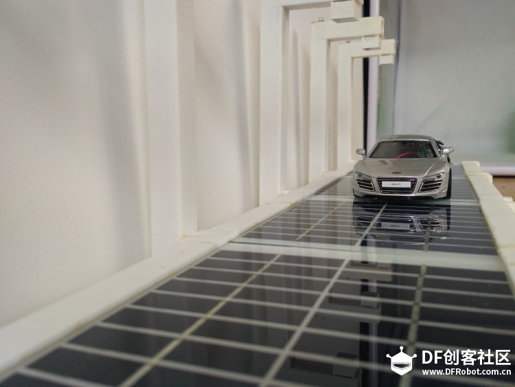
Therefore, we designed and made a wireless power-supply smart road base on IoT platform.
Functional design:
1. Photovoltaic conversion; the solar panel is paved on the road surface to convert the collected optical energy into electric energy and charge the battery pre-buried underground.
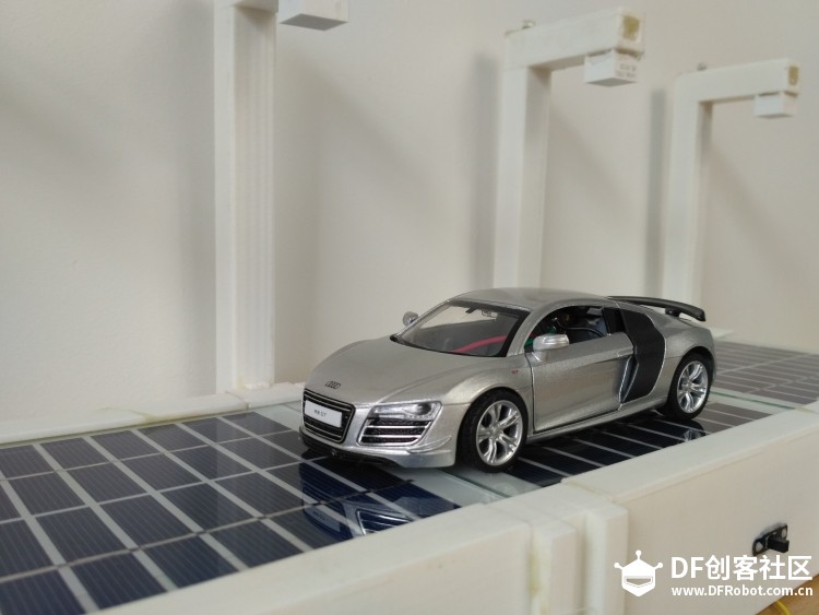
2. Wireless charging; the wireless charging environment is provided to the electric vehicles on the road surface to ensure the vehicles on the road surface can be charged anytime.
3. Smart lighting; the lights on the road can be automatically switched on and off according to the change of external light conditions to guarantee lighting and energy saving.
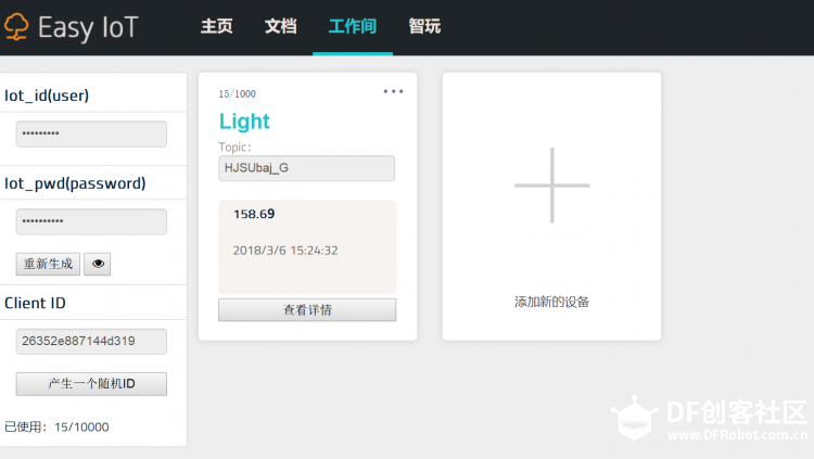
4. Internet of Things; the light sensor set on the road is connected to the Internet of Things, allowing to check the road light through mobile phone and PC terminal real-timely.
5. Artificial intelligence; big data analysis is generated through collection of IoT data, enabling the road to control the road lighting automatically to achieve artificial intelligence control. (conception)
Components List:
1. Solar Panel (9v 220mA) *4
2. 3.7V Lipo Battery *4
3. Wireless Charging Module 5V/1A *4
4. Micro Usb Charging module *4
5. Photoresistance *5
6. 10K resistance *5
7. 5mm LED Pack (50 pcs) *5pcs
8. DFRduino UNO R3 - Arduino Compatible *1
9. Gravity: UART OBLOQ – IOT Module (Microsoft Azure) *1
10. DuPont Line
Product making:
I. Wireless power supply road part
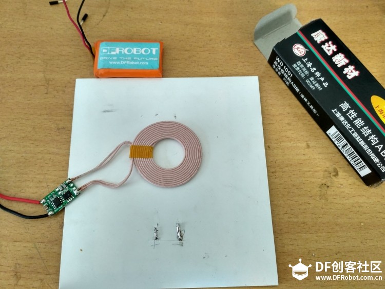
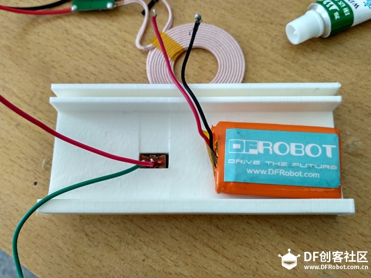
Use four polycrystalline silicon battery plates as the road surface to convert the collected light energy to electric energy. Weld positive and negative poles of battery plate with the In+ and in- of Micro USB charging module, weld the positive and negative poles of wireless charge transmitting terminal with out+ and out- of Micro USB charging module, and weld the positive and negative poles of 3.7 lithium battery with B+, B- of Micro USB charging module.
To obtain the relatively average energy on the surface of each plate of battery plate, we pasted the transmitting coil at the central position of battery plate.
In addition, we also added a switch in the lithium battery circuit for controlling the on/off of energy.
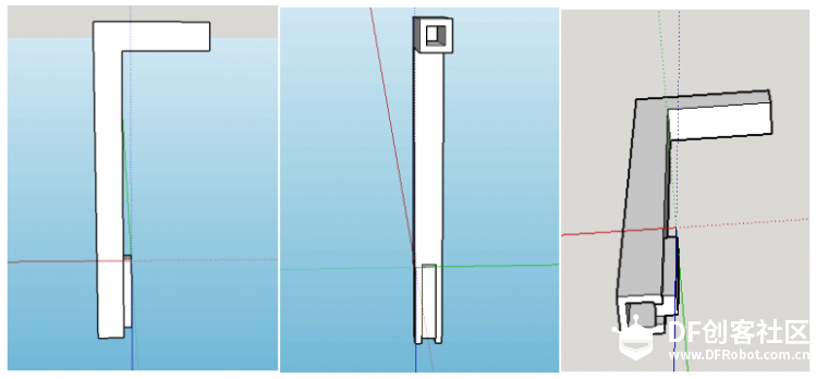
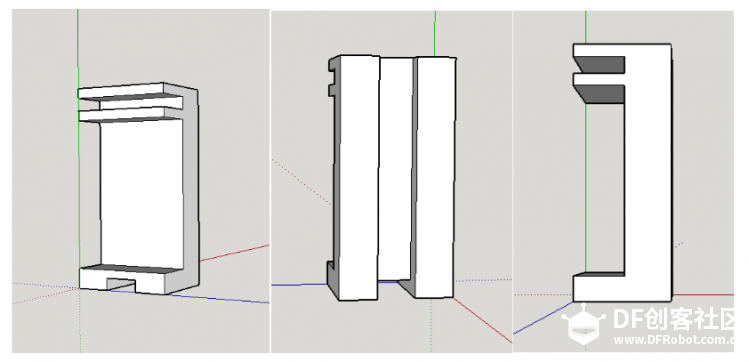
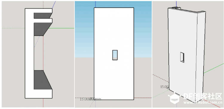
To simulate the road conditions, we printed structural parts such as highway subgrade, lamp post, lamp post support frame through 3D modeling. The modeling of structural parts as shown in the figure below was finished in Sketchup:
Lamp post:
Lamp post support frame
Subgrade model:
Smart road lamp part
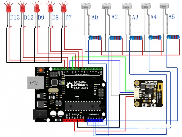
The on/off of smart road lamp is controlled by setting the value of light intensity through several light sensors. The energy is used scientifically and reasonably provided that the road surface lighting is guaranteed. We used a photoresistor here to obtain a stable serial port value. A 10K ohm resistor is added to it, and all welded positions are wrapped with heat shrink tubing to ensure electrical isolation.

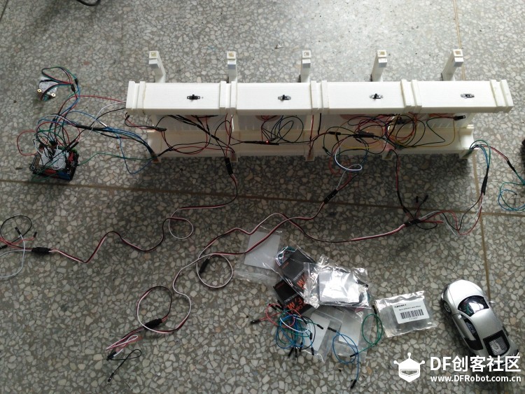
The hardware circuit connection is as shown in the figure below. 5 LEDs are connected to D13, D12, D9, D8, D7 respectively; light sensor is connected to A0, A2, A3, A4, A5; corresponding green line of IoT module T is connected to D 10 and corresponding blue line of R is connected to D11.
Internet of Things part
Installation test
Install dial switch on the subgrade
Put the subgrade at both sides of battery plate and fix it with glue. Meanwhile, place the road lamp and lamp support at the appropriate position. Finish the installation of other modules in the same method.
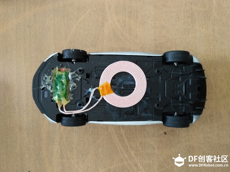
Modify the electric vehicle model to change the original power supply with battery to power supply with wireless receiving coil.
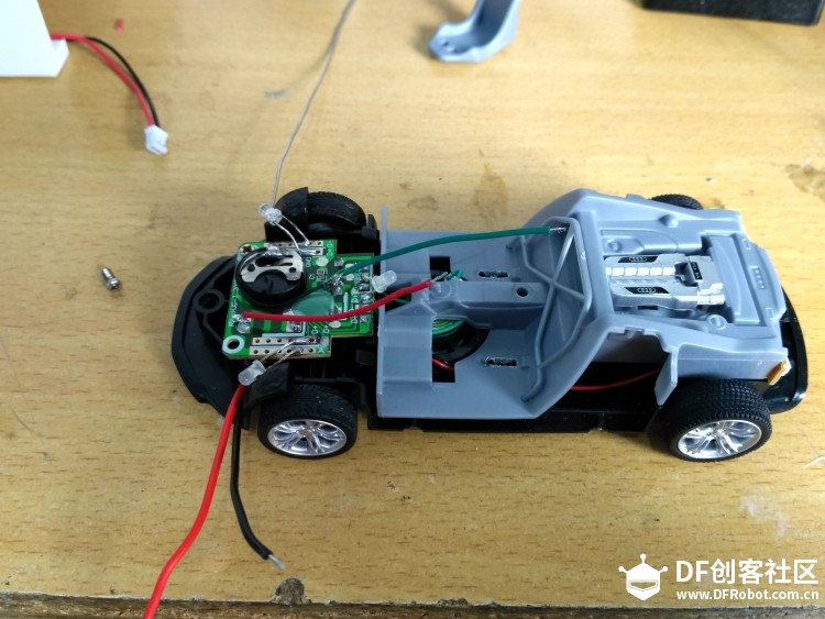
Power on test
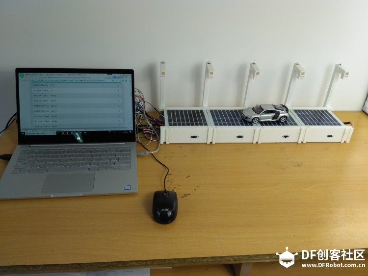

Power on test
Recent Blogs

Hands-On Test of 6 New 4K USB Cameras: Resolution, Color, Field of View, and Compatibility
Compare six 4K USB cameras using IMX415, IMX274, and IMX678 sensors across resolution, color, field of view, distortion, Linux, and low-light tests.
REVIEWS Jul 23 2026

Fermion BMI323 6-Axis IMU Engineering Test Notes: Accelerometer, Gyroscope, Step Counter, and I2C Address Verification
This article is an engineering test note, mainly intended to demonstrate the actual performance of the module in common development scenarios, rather than a laboratory calibration report.
REVIEWS Jul 15 2026

Meet DFRobot at FAB26 Boston 2026: AI, Open-Source Hardware & Maker Education
Visit DFRobot at FAB26 Boston for hands-on AI workshops, open-source hardware demos, and practical insights into K–12 maker education.
NEWS Jul 15 2026