New: seeMote Cube for visionOS Developers - Build physical input for Apple Vision Pro apps. Learn More ›
TUTORIALS Robotics
Line Tracking (Following) Sensor For Arduino × 3
Width 2.5CM Black Electrical Tape × 1

1M*1M White Board × 1

M3*30MM Nylon support (screws, nuts) × 3 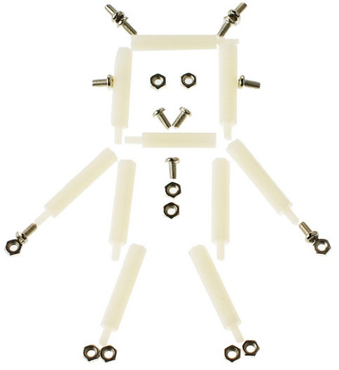
Plug in your USB. Download the Arduino code, named “HuntingLineBlack.ino”, from GitHub. Click the Upload button in the Arduino IDE to upload the code to your BLE control board.

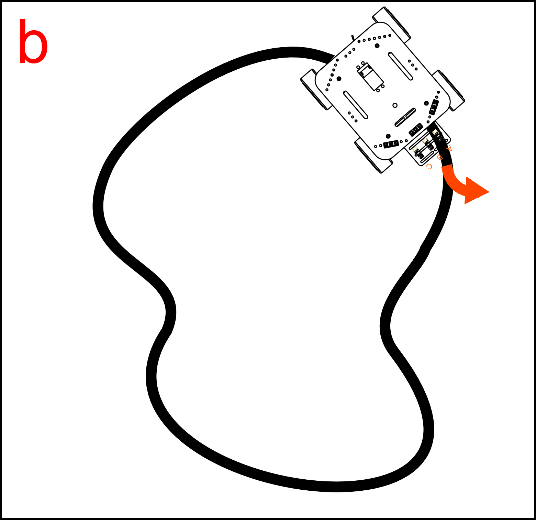
Take out your whiteboard. Use your 2.5 cm wide electrical tape to lay out a path on the whiteboard as shown in the below picture.

The width of the wire is roughly 2.5 cm, the approximate distance between sensors A and C. We’ve chosen the path above for reasons relating to code; a later section will explain this reasoning more thoroughly.


if (MiddleValue==LOW) { //line in the middle
Conversely, if the sensors detect the black line/track to the right while also detecting white space to the left, the robot will turn right. See Example C below:
How To Build A Robot - Lesson 3: Build A Line Tracking Robot
DFRobot
Dec 08 2016 268121
After completing the basic functions, we’re now ready to give the Arduino robot an upgraded capability - Line-tracking!
In this tutorial, you’ll be taught step by step to make a line tracking Arduino robot. To make this tutorial easy to follow, an Arduino robot kit (Pirate: 4WD Arduino Mobile Robot Kit with Bluetooth 4.0 ) is used here as an example.
Lessons Menu:
Lesson 1: Introduction
Lesson 2: Build a Basic Arduino Robot
Lesson 3: Build a Line Tracking Arduino Robot
Lesson 4: Build an Arduino Robot That Could Avoid Obstacles
Lesson 5: Build an Arduino Robot With Light And Sound Effects
Lesson 6: Build an Arduino Robot That Could Monitor Environment
Lesson 7: Build a Bluetooth-Controlled Arduino Robot
Hardware Parts You May Need:

Assembly Instructions
It is not difficult to assemble the Arduino robot. Please follow the following instruction.
Step 1:
Firstly, you need 3 nylon supports and their accompanying screws and nuts.

Step 2: Attaching the Nylon supports
Using nuts, attach the nylon supports on top of the Mini sensors. When attaching the supports, please pay attention to their direction: the nuts and probes should both be in one direction.

Step 3: Assembling the sensor board
Remove the upper plate from the robotic platform. Then, attach the sensor board to the front of the platform.

Step 4: Assembling the line tracking sensor
First, connect the sensor with the wire designated for data transmission. Then, use your M3 screws to affix the sensors to the expansion board protruding from the front of the platform.


Connecting the hardware
After assembling the sensors, don’t rush to put the platform’s upper plate back on – before doing that, we need to first connect the sensors with the Romeo BLE.
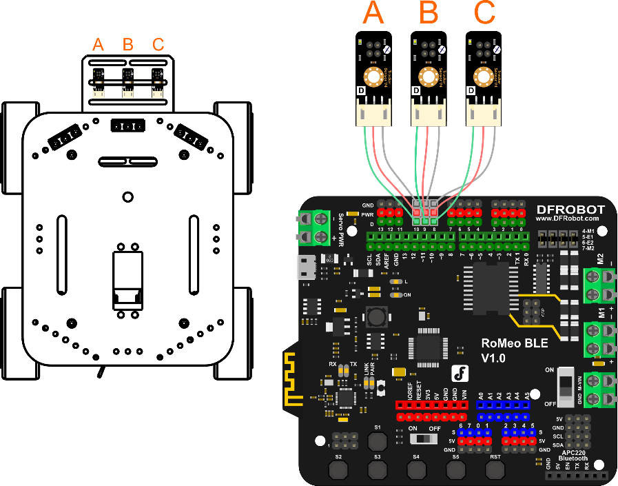
The picture on the left-hand side shows the correct ABC placement of the sensors on the sensor board, which corresponds to pins 10, 9, and 8 on the Romeo BLE. When connecting the sensors, be sure to check that you’ve connected them in the proper sequence. After connecting the sensors, re-attach the platform’s upper plate back atop the base.

Adjusting the sensors
Before downloading code, we need to adjust our sensors. First, plug a USB cable into your Romeo BLE (Arduino Robot Control Board with Bluetooth 4.0) to give it power. As seen in the below picture, the sensor below has a Philips screw head; this screw head can be used to adjust the sensor’s detection of distance. Take a white piece of paper and place it beneath the sensor’s probe (the color of the paper is used for calibration purposes). Get a screwdriver and use it to tighten the Philips screw head. You’ll feel the sensor’s probe physically move up and down depending on how tightly you tighten the screw head. You’ll also see the sensor’s LED light up as soon as you start tightening. Tighten the screw head until the probe point is around 2 cm above the piece of paper.

Coding
Plug in your USB. Download the Arduino code, named “HuntingLineBlack.ino”, from GitHub. Click the Upload button in the Arduino IDE to upload the code to your BLE control board.
Configuring your Arduino Robot’s path
Take out your whiteboard. Use your 2.5 cm wide electrical tape to lay out a path on the whiteboard as shown in the below picture.
The width of the wire is roughly 2.5 cm, the approximate distance between sensors A and C. We’ve chosen the path above for reasons relating to code; a later section will explain this reasoning more thoroughly.
Transmission: How it works
How do we make the robot stay on its track? We need to ensure that the robot is consistently located in the middle of the track. The robot uses its 3 transmission sensors to calibrate its position relative to the track -- once it veers to the side, the robot will self-adjust back towards the middle.
When Our robot moves, three conditions will happen.
(a)When the robot first begins moving along the track, only the middle sensor (B) detects the black line – the left and right sensors have not come into play yet. The car will remain centered along the track and move forward.
(b)After continuing on its track, the robot might start to veer off center. Under these circumstances, the left and right sensors will try to detect the black line and self-guide the robot back towards the track. For instance, if the robot veers towards the right side of the track, the car will need to re-center itself by turning towards the left – the left sensor will kick in and automatically turn the robot until it re-centers.


(c)Conversely, if the robot veers towards the left side of the track, the right sensor will kick in and adjust the robot’s path until it re-centers.
Code Synopsis
There’s no need to discuss the basic code – let’s just take a look at the part involving transmission.
int RightValue; //Right line tractor sensor on Pin 8
int MiddleValue; //Middle line tractor sensor on Pin 9
int LeftValue; //Left line tractor sensor on Pin 10
//reading 3 pins values of Line Tracking Sensor
RightValue=digitalRead(8);
MiddleValue=digitalRead(9);
LeftValue=digitalRead(10);
Use three variables – RightValue, MiddleValue, LeftValue – to record the 3 sensors’ read values.
The digitalRead(pin) function is used to read the digital Input/Output port value. If this part is still unclear, please check out our Terminology Manual or the Arduino website.
When the middle transmission sensor detects a black line (the track), it’ll produce a LOW energy output. When they detect a white space, they’ll produce a HIGH energy output.
Example A below illustrates the transmission code’s working principles. When the middle sensor detects a black line (the track), it’ll produce a LOW energy output. When the left/right sensors detect white space, they’ll produce a HIGH output.
if (MiddleValue==LOW) { //line in the middle
Robot.Speed (100,100);
delay(10);
}
else if ((LeftValue==HIGH) && (RightValue==HIGH)) {
Robot.Speed (100,100);
delay(10);
}
If the sensors detect the black line/track to the left while also detecting white space to the right, the robot will turn left. See Example B below:
else if ((LeftValue==LOW)&&(RightValue==HIGH)){
Robot.Speed (-100,100); //turn left
delay(10);
}
Conversely, if the sensors detect the black line/track to the right while also detecting white space to the left, the robot will turn right. See Example C below:
else if ((LeftValue==HIGH)&&(RightValue==LOW)){
Robot.Speed (100,-100); //turn right
delay(10);
}
Related Product


Recent Blogs

Hands-On Test of 6 New 4K USB Cameras: Resolution, Color, Field of View, and Compatibility
Compare six 4K USB cameras using IMX415, IMX274, and IMX678 sensors across resolution, color, field of view, distortion, Linux, and low-light tests.
REVIEWS Jul 23 2026

Fermion BMI323 6-Axis IMU Engineering Test Notes: Accelerometer, Gyroscope, Step Counter, and I2C Address Verification
This article is an engineering test note, mainly intended to demonstrate the actual performance of the module in common development scenarios, rather than a laboratory calibration report.
REVIEWS Jul 15 2026

Meet DFRobot at FAB26 Boston 2026: AI, Open-Source Hardware & Maker Education
Visit DFRobot at FAB26 Boston for hands-on AI workshops, open-source hardware demos, and practical insights into K–12 maker education.
NEWS Jul 15 2026