New: seeMote Cube for visionOS Developers - Build physical input for Apple Vision Pro apps. Learn More ›
TUTORIALS micro:bit The objective of this esp32 tutorial is to explain how to create a simple Hello World application for the micro:bit board, using the JavaScript Blocks Editor.
NOTE: This article is written by Nuno Santos who is an kindly Electronics and Computers Engineer. live in Lisbon, Portugal. you could check the original article here.
Related Blog Post:
Micro:bit board: an introduction
Mobile Doorbell System with BOSON and Micro:bit
micro:bit JavaScript Blocks Editor: Hello World
DFRobot
Oct 13 2017 263611
The objective of this esp32 tutorial is to explain how to create a simple Hello World application for the micro:bit board, using the JavaScript Blocks Editor.
Introduction
The objective of this post is to explain how to create a simple Hello World application for the micro:bit board, using the JavaScript Blocks Editor. You can read more about the micro:bit board at this previous post.
Note that even if you don’t have the micro:bit board yet, you can still test the code shown on this tutorial on the editor simulation environment, as we will see below.
For this tutorial we will be sending our “Hello World” message to the serial port in a loop. Thus, in order for our computer to detect the micro:bit board as a serial device, we need to install a driver, which can be found here. You can read more about reading the serial output of micro:bit in a computer here.
Although the online editor supports a drag and drop interface, we will develop our code in the JavaScript mode.
The code
Writing content to a serial connection is very easy on this environment. To do it, we simple need to call the writeString function of the serial namespace and pass as input argument the string we want to write.
serial.writeString("Hello World\n");
You can read more about namespaces here, but they are basically used to aggregate groups of functions that have similar functionality. So, the serial namespace, for example, aggregates multiple functionalities related with writing to the serial port.
Now we will use another namespace, the basic, and call a function called forever. The forever function receives as input another function, which will keep running in the background [1].
Although we could have used a simple while loop to keep printing our “Hello World” message, we are analyzing the forever function since it is widely used in many micro:bit examples. Furthermore, for those with a previous background in Arduino, it pretty much feels like the main loop.
Another interesting thing to mention is that if we drag the forever function from the basic block in the left side of the code editor, it will have the format shown below.
basic.forever(() => {
   // Code goes here
});
So, as can be seen, it is passing a () => { } construct as input of the forever function. Nonetheless, as I’ve previously mentioned, the forever function receives a JavaScript function which, as can be seen here, is usually declared with other type of syntax.
So, what we are actually doing with the () => { } notation is passing as input of the forever function an arrow function. This is a more advanced concept of JavaScript that we will not analyse in detail in this introductory post, but it is basically another way of declaring functions, although it has a couple of diferences.
Nonetheless, if you feel more comfortable with the definition of named functions using the function keyword construct, these can also be used as input argument of the forever function.
To finalize and to avoid having our code constantly writing to the serial port, we will use the waitMicros function of the control namespace, which will block the execution for the number of microseconds specified as input.
The final complete code can be seen below, with this additional call to the waitMicros function, which will introduce a delay of 40000000 microseconds, which is equivalent to 4 seconds.
basic.forever(() => {
    control.waitMicros(4000000);
    serial.writeString("Hello World\n");
});
You can check below at figure 1 how the final code looks like on the JavaScript edito
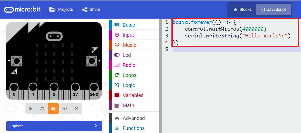
Figure 1 – JavaScript final code on the Blocks Editor.
If we change the view to the Blocks editor, we can check how the corresponding code looks like in that format. You can check below at figure 2.

Figure 2 – Corresponding code in the Blocks editor.
Simulating the code
Before actually uploading the code to the board, it is possible to simulate it in the JavaScript Blocks Editor. This is a great way to make a quick test before uploading the code to the board. It also allows us to experiment with the environment before actually buying the board.
So, to start the simulation, just click on the start button below the image of the board, which is highlighted in figure 3.

Figure 3 – Starting the simulation of the Hello World program.
Upon starting the simulation, you should see a text box bellow, as shown in figure 4, which shows the message we defined being printed. Note that in the simulation the delay between the messages will not be the one we specified in the waitMcros function, but it will be correct once we upload the code to the board.

Figure 4 – Output of the simulation.Note that the small number that appears left to the “Hello World” message corresponds to the number of messages that have been already printed at a given moment.
Running the code on the board
To run the code on the board, we first need to download the binary file from the editor. To do so, just click the big download button on the bottom of the editor, as highlighted in figure 5.

Figure 5 – Downloading the code to a computer.To upload the code to the board, simple open the location to where the file was downloaded on your computer and drag it to the board drive location. If you are on Windows, the normal copy popup showing the progress will appear, similarly to when we copy files to a flash drive.
The code will start running automatically. To get the output, we just need to establish a serial connection to the device using a suitable software. In my case I’m using the Arduino IDE, since it allows me to easily see which COM devices are available. Nonetheless, there are plenty of other options, being one very good option Putty.
If you are having troubles figuring to which COM port your micro:bit board was assigned, you can go do Windows Device Manager and under Ports (COM & LPT) you should find your micro:bit board under the name mbed Serial Port, as can be seen below on figure 6.

Figure 6 – Finding the micro:bit COM port on the device manager of Windows.
After establishing a successful serial connection to the micro:bit board, you should receive an output similar to figure 7, which shows the message we have defined being printed.

Figure 7 – Output of the micro:bit program.In order to be able to get the output, we need to set the baud rate in the program used to interact with the board to 115200, which is the default baud rate used by the serial module of micro:bit.
NOTE: This article is written by Nuno Santos who is an kindly Electronics and Computers Engineer. live in Lisbon, Portugal. you could check the original article here.
He had written many useful tutorials and projects about ESP32, ESP8266, microbit, If you are interested, you could check his blog to know more.
Related Blog Post:
Microbit Tutorials
Micro:bit board: an introduction
5 Easy Steps for you to Quick Start with BBC Microbit
Micro:bit JavaScript Blocks Editor: Hello World
Micro:bit JavaScript Blocks Editor: Turning LEDs on and off
Micro:bit JavaScript Blocks Editor: Detecting button click events
Micro:bit JavaScript Blocks Editor: String interpolation
Micro:bit: MicroPython support
Microbit Projects
Mobile Doorbell System with BOSON and Micro:bit
How To Make A Micro:bit Heart Rate Monitor
Microbit Project micro:bit Laser Target
Micro:bit Surprise box
Microbit Project: Micro:bit Selfie Remote
Micro:bit Project: Light(Mood Lamp)
Micro:bit Project: Yes/No Bear
Smart Fan Control System with Micro:bit
LED writing board (micro:bit compatible)
micro:bit car with DFRobot gamepad
OBLOQ-IoT Module +Micro:bit IoT Flower Watering
Related Product

Recent Blogs

Hands-On Test of 6 New 4K USB Cameras: Resolution, Color, Field of View, and Compatibility
Compare six 4K USB cameras using IMX415, IMX274, and IMX678 sensors across resolution, color, field of view, distortion, Linux, and low-light tests.
REVIEWS Jul 23 2026

Fermion BMI323 6-Axis IMU Engineering Test Notes: Accelerometer, Gyroscope, Step Counter, and I2C Address Verification
This article is an engineering test note, mainly intended to demonstrate the actual performance of the module in common development scenarios, rather than a laboratory calibration report.
REVIEWS Jul 15 2026

Meet DFRobot at FAB26 Boston 2026: AI, Open-Source Hardware & Maker Education
Visit DFRobot at FAB26 Boston for hands-on AI workshops, open-source hardware demos, and practical insights into K–12 maker education.
NEWS Jul 15 2026