Holiday Notice: We're away from Apr 30 to May 5, but our store is open 24/7! All orders placed now will be promptly processed and shipped on May 6.
Gestr: A Smart Glove for Speech Impairments
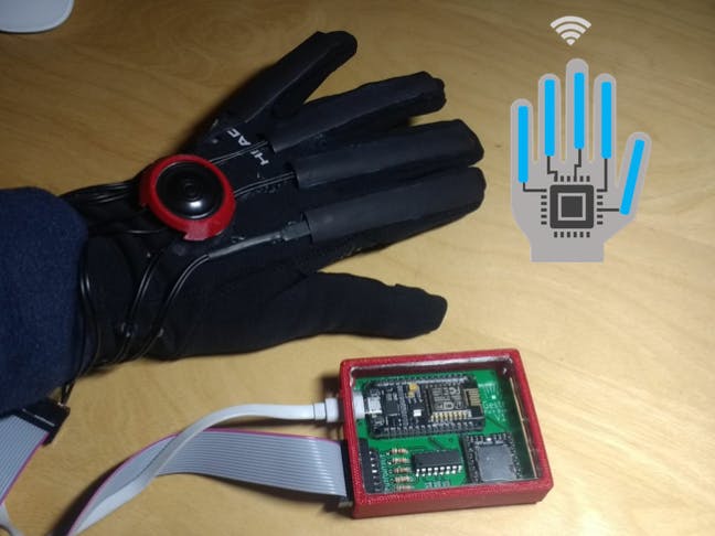
Gestr is a sensor-equipped glove which can convert hand gestures and signals to spoken text for people with speech impairments.
Things used in this project
Hardware components
NodeMCU ESP8266 Breakout Board
DFRobot DFplayer
Flex Sensor
4051 Multiplexer
Custom PCB
Glove
16 Pin Ribbon Cable
Speaker: 0.25W, 8 ohms
Male-Header 16 Position 2 Row Right Angle
Resistor 10k ohm
DIP 16 IC Socket
Female Header 8 Position 1 Row (0.1")
Female Header 15 Position 1 Row (0.1")
Software apps and online services
Arduino IDE
Hand tools and fabrication machines
3D Printer (generic)
Laser cutter (generic)
Soldering iron (generic)
Hot glue gun (generic)
Story
Inspiration
Gestr was inspired by my father's teacher and mentor, Mr. Lenny. Due to a brain hemorrhage, Mr. Lenny was paralyzed from his right side and lost his ability to speak. He has been bedridden and has not spoken to his family since 2013, due to his condition.
People such as Mr. Lenny, who are partially paralyzed or unable to speak have become alienated from society as they are unable to communicate with others efficiently. This issue of speech impairment is prevalent across the world, with nearly 70 million people in the world having speech impairments. A current day solution to this is sign language, but this is not universal and is difficult for people to learn. To bridge this gap, Gestr was created.
Gestr is able to convert hand gestures and signals to spoken text, connecting people with speech impairments to their loved ones.
The Multiplexer IC (74HC4051N)
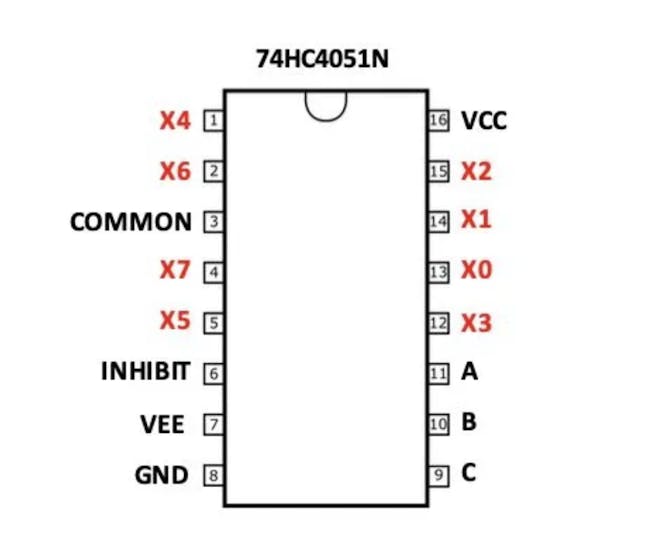
While the Node-MCU is packed with excellent features such as WiFi and Arduino IDE compatibility, it has its drawbacks. It only has one analog pin, which is insufficient for this project. Since the glove has five flex sensors, it requires five analog inputs to work. A simple and inexpensive solution to this problem is to use a Multiplexer IC (74HC4051N). This IC is able to convert one analog input into eight!
How Does it Work?
The IC works by turning on one analog input, reading it, and turning it off. It then turns on the next analog input. By doing this, it only reads one sensor at a time, sending it to the micro controller's analog pin. The IC is able to turn on, read, and turn off the analog inputs so quickly that it seems as though it is reading them all at the same time. This is similar to how computer and smartphone screens work; Each pixel cannot have its own designated pin (that would be a disaster!), so it turns the pixels on and off so fast that our eyes perceive all of them as on at the same time. To function, the IC needs three digital pins. By changing the combinations of the on and off states of the pins, the IC is able to turn on and off all 8 analog inputs.
PCB Schematic
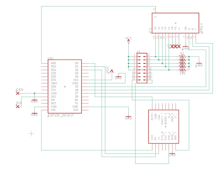
The PCB schematic was created in Autodesk Eagle and is as shown in the image above. All Eagle files are in this project and can be downloaded.
PCB Board Layout
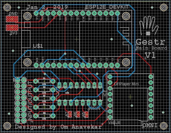
Here is my PCB design. All the Eagle files for this circuit board are in the attachments section, so you can use or modify this design to build your own PCB! I have added SMD pads for the extra 3 analog inputs as well as the 3V3 and GND port. This will allow me to expand this system if I ever need to, saving resources and time and making the PCB versatile.
Soldering and Assembly
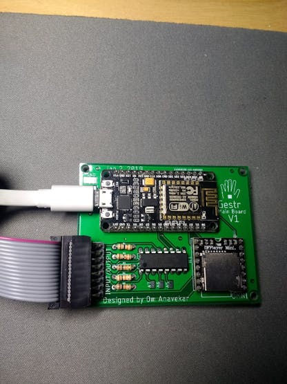
After waiting a couple of days, I finally got my PCBs in the mail. Now it's time for the fun part, soldering it all together! By following the schematic, soldering the PCB was fairly easy. In my design, I soldered the chips directly to the board. If you want to reuse or replace the chips in the future, an IC socket and female headers can be used, but this will result in a larger form factor.
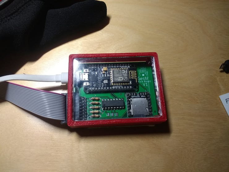
An enclosure for the control board was created to house the PCB. A piece of acrylic was laser cut so that the PCB was viewable, but this step is optional.
To mount the sensors onto the glove, I glued rubber tubes to the fingers of the glove and placed the sensors inside each. To mount the speaker, a speaker holder was 3D printed and adhered onto the top of the glove. All thee sensor cables went the wrist of the glove, where they were connected to the ribbon cable which led to the control board.
_bCoSLignGP.jpeg?auto=compress%2Cformat&w=740&h=555&fit=max)
Setting It Up
For my system, I put 5 mp3 files onto a micro SD card and inserted it into the SD card slot on the DF player. Each mp3 file plays a prerecorded message.
0001.mp3 = "I need assistance"
0002.mp3 = "I need to use the restroom"
0003.mp3 = "May I have some water?"
0004.mp3 = "May I have some food?"
0005.mp3 = "I need help!"
For the code, I made specific hand signals play specific MP3 files.
#include <DFPlayer_Mini_Mp3.h>
#include <SoftwareSerial.h>
#include <Wire.h>
#define PIN_BUSY D0
SoftwareSerial mp3Serial(D1, D2); // RX, TX
const int MUX_A = D5;
const int MUX_B = D6;
const int MUX_C = D7;
const int ANALOG_INPUT = A0;
int valueF1 = 0;
int valueF2 = 0;
int valueF3 = 0;
int valueF4 = 0;
int valueF5 = 0;
void setup() {
 pinMode(MUX_A, OUTPUT);
 pinMode(MUX_B, OUTPUT);
 pinMode(MUX_C, OUTPUT);
 Serial.begin(115200);
 pinMode(PIN_BUSY, INPUT);
 Serial.begin (115200);
 Serial.println("Setting up software serial");
 mp3Serial.begin (9600);
 Serial.println("Setting up mp3 player");
 mp3_set_serial (mp3Serial);
 delay(1000);
 mp3_set_volume (20);
}
void changeMux(int c, int b, int a) {
 digitalWrite(MUX_A, a);
 digitalWrite(MUX_B, b);
 digitalWrite(MUX_C, c);
}
void readValues() {
 float value;
 changeMux(HIGH, LOW, LOW);
 valueF1 = analogRead(ANALOG_INPUT);
 Serial.print("F1: "); Serial.print(valueF1); Serial.print(" ");
 changeMux(LOW, LOW, HIGH);
 valueF2 = analogRead(ANALOG_INPUT);
 Serial.print("F2: "); Serial.print(valueF2); Serial.print(" ");
 changeMux(LOW, HIGH, LOW);
 valueF3 = analogRead(ANALOG_INPUT);
 Serial.print("F3: "); Serial.print(valueF3); Serial.print(" ");
 changeMux(LOW, HIGH, HIGH);
 valueF4 = analogRead(ANALOG_INPUT);
 Serial.print("F4: "); Serial.print(valueF4); Serial.print(" ");
 changeMux(LOW, LOW, LOW);
 valueF5 = analogRead(ANALOG_INPUT);
 Serial.print("F5: "); Serial.print(valueF5); Serial.println(" ");
 delay(200);
}
void loop() {
 readValues();
 if (valueF5 <= 60 && valueF5 > 40) {
      Serial.println("Stop");
 mp3_play (1);
 Serial.print("Busy: ");
 Serial.println(digitalRead(PIN_BUSY));
 delay(500);
 delay (1000);
 }
 if (valueF5 <= 40 && valueF4 <=40) {
      Serial.println("Stop");
 mp3_play (2);
 Serial.print("Busy: ");
 Serial.println(digitalRead(PIN_BUSY));
 delay(500);
 delay (1000);
 }
   if (valueF1 <= 40 && valueF5 <=40) {
      Serial.println("Stop");
 mp3_play (3);
 Serial.print("Busy: ");
 Serial.println(digitalRead(PIN_BUSY));
 delay(500);
 delay (1000);
 }
 if (valueF2 <= 40 && valueF3 <=40 && valueF4 <=40) {
      Serial.println("Stop");
 mp3_play (4);
 Serial.print("Busy: ");
 Serial.println(digitalRead(PIN_BUSY));
 delay(500);
 delay (1000);
 }
 if (valueF3 <= 40 && valueF4 <=40) {
      Serial.println("Stop");
 mp3_play (5);
 Serial.print("Busy: ");
 Serial.println(digitalRead(PIN_BUSY));
 delay(500);
 delay (1000);
 }
}
Below is the device in action!
FutureEnhancements:
Integration with an IR remote to control devices such as TVs.
Add a "calibrate" feature, where a caretaker speaks into a microphone as a patient does a hand gesture, allowing the system to "learn" new hand gestures.
Usage of an accelerometer to collect readings on hand movements.
A system in which a caretaker gets a notification on his/her device when a patient needs assistance.
A system for a patient to call emergency services if there is a problem.
Interaction with a smart speaker such as Amazon Echo or Google Home.
Conclusion
Gestr is a simple, cost-effective device for people with speech impairments. As it is still in development, many features have yet to be refined. We are hoping to launch Gestr before 2020, as we understand the great positive benefits this device can offer to people who are suffering from speech impairments. Through the use of this device, we hope to connect the gap between those who cannot speak and those who can.
Custom parts and enclosures
Code
#include <DFPlayer_Mini_Mp3.h>
#include <SoftwareSerial.h>
#include <Wire.h>

#define PIN_BUSY D0

SoftwareSerial mp3Serial(D1, D2); // RX, TX

const int MUX_A = D5;
const int MUX_B = D6;
const int MUX_C = D7;

const int ANALOG_INPUT = A0;

int valueF1 = 0;
int valueF2 = 0;
int valueF3 = 0;
int valueF4 = 0;
int valueF5 = 0;

void setup() {

  pinMode(MUX_A, OUTPUT);
  pinMode(MUX_B, OUTPUT);
  pinMode(MUX_C, OUTPUT);

  Serial.begin(115200);

  pinMode(PIN_BUSY, INPUT);
  Serial.begin (115200);
  Serial.println("Setting up software serial");
  mp3Serial.begin (9600);
  Serial.println("Setting up mp3 player");
  mp3_set_serial (mp3Serial);
  delay(1000);
  mp3_set_volume (20);
}


void changeMux(int c, int b, int a) {
  digitalWrite(MUX_A, a);
  digitalWrite(MUX_B, b);
  digitalWrite(MUX_C, c);
}
void readValues() {
  float value;
  changeMux(HIGH, LOW, LOW);
  valueF1 = analogRead(ANALOG_INPUT);
  Serial.print("F1: "); Serial.print(valueF1); Serial.print(" ");

  changeMux(LOW, LOW, HIGH);
  valueF2 = analogRead(ANALOG_INPUT);
  Serial.print("F2: "); Serial.print(valueF2); Serial.print(" ");

  changeMux(LOW, HIGH, LOW);
  valueF3 = analogRead(ANALOG_INPUT);
  Serial.print("F3: "); Serial.print(valueF3); Serial.print(" ");

  changeMux(LOW, HIGH, HIGH);
  valueF4 = analogRead(ANALOG_INPUT);
  Serial.print("F4: "); Serial.print(valueF4); Serial.print(" ");

  changeMux(LOW, LOW, LOW);
  valueF5 = analogRead(ANALOG_INPUT);
  Serial.print("F5: "); Serial.print(valueF5); Serial.println(" ");

  delay(200);

}

void loop() {
  readValues();
  if (valueF5 <= 60 && valueF5 > 40) {
       Serial.println("Stop");
  mp3_play (1);
  Serial.print("Busy: ");
  Serial.println(digitalRead(PIN_BUSY));
  delay(500);
  delay (1000);
  }

  if (valueF5 <= 40 && valueF4 <=40) {
       Serial.println("Stop");
  mp3_play (2);
  Serial.print("Busy: ");
  Serial.println(digitalRead(PIN_BUSY));
  delay(500);
  delay (1000);
  }

    if (valueF1 <= 40 && valueF5 <=40) {
       Serial.println("Stop");
  mp3_play (3);
  Serial.print("Busy: ");
  Serial.println(digitalRead(PIN_BUSY));
  delay(500);
  delay (1000);
  }


  if (valueF2 <= 40 && valueF3 <=40 && valueF4 <=40) {
       Serial.println("Stop");
  mp3_play (4);
  Serial.print("Busy: ");
  Serial.println(digitalRead(PIN_BUSY));
  delay(500);
  delay (1000);
  }


  if (valueF3 <= 40 && valueF4 <=40) {
       Serial.println("Stop");
  mp3_play (5);
  Serial.print("Busy: ");
  Serial.println(digitalRead(PIN_BUSY));
  delay(500);
  delay (1000);
  }


}

Unlock advanced smart home automations with the $8.9 DFRobot C4002 mmWave sensor. Learn to extract raw speed, energy, and direction data using ESPHome.
REVIEWS
Need an ORP sensor? We compare entry-level Arduino meters, 24/7 online probes, and IP68 industrial RS485 sensors to help you build the best water IoT system.
SELECTION GUIDE
This guide provides a side-by-side comparison and selection analysis for 5 core Electrical Conductivity (EC) sensors from DFRobot, helping you quickly identify the most suitable product based on measurement range (K-value), application scenario (industrial/laboratory), and system architecture (Analog/RS485).
SELECTION GUIDE