PROJECTS Arduino In this post, we would introduce readers to using the built-in acceleration meter and gyro sensor on Arduino 101 combined with the electronic control to make a self balancing robot.
Hardware components:
Small Segway with Arduino 101
DFRobot
Mar 20 2018 260378
Introduction
In October 2015, Arduino and Intel released a development board called the Arduino 101, which equipped with the core of x86, BLE(Bluetooth Low Energy), and IMU(Inertial Measurement Unit).
In this post, we would introduce readers to using the built-in acceleration meter and gyro sensor on Arduino 101 combined with the electronic control to make a self balancing robot.
This tutorial is divided into 5 detail steps below, let's take a look at how to complete this project!
Hardware components:
Arduino 101 & Genuino 101
3mm acrylic board for laser cut frame
DC motor (generic)
Solderless Breadboard Half Size
Jumper wires (generic)
TA7279P motor driver IC
3.7V lithium rechargeable battery
STORY
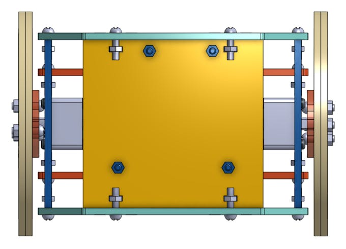
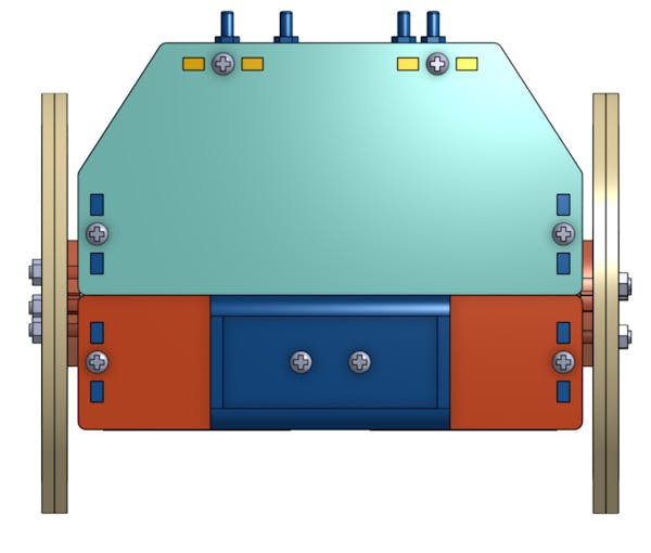
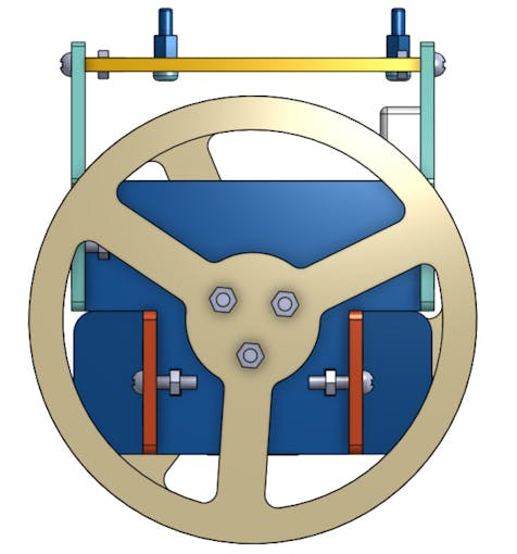
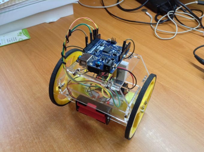
1. Building A Balancing Robot
In this sample, the self balancing robot is mainly composed of laser cutting acrylic board. The thickness of acrylic board is 3mm, and we would use metal roses and nuts to assembly the cases of the body. The motor on the robot is two small 5V DC gear motors, and the wheels are made of acrylic board too. The tire of the wheel is simply a layer of non-slip mat. There are two battery holder in the two sides under the bottom of the robot, each one has two 3.7v lithium battery in it. The one battery is used to support the controller, and the other one is to drive the motors. We have shared the complete CAD file on Onshape, readers can just click the link to obtain it (note that you might need a Onshape account to view it).


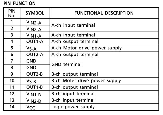
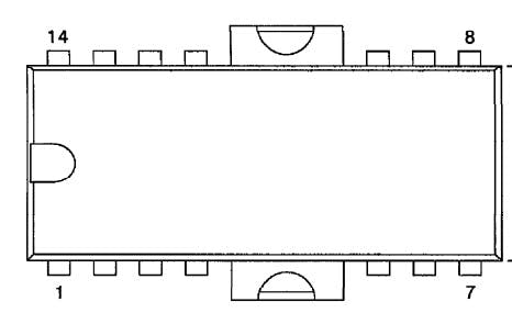
2. Circuits
The motor driver chip used in this post is TA7279P, the pinout diagram and the corresponding function are shown below(refers to this official datasheet). Please connect the pin 5 and pin 10 to the power of lithium battery, and connect the signal input pins of A and B channels (i.e. Pin 1, 3, 12, 13) to pin 3, 5, 6, 9 on Arduino respectively. We would use these pins to output PWM signal to control the power of motors. To drive the motors, just connect the output pins in the list to the motors directly. For example, if you want channel A to control the left motor and channel B to control the other side, please plugs pin 4 and 6 to the left one and pin 9 and 11 to the right one. In addition, this chip demands a proper working voltage, one can just plug the 14 to 5V power supply on the Arduino board and connect pin 7 to the ground wire.
3. Arduino 101 SDK in Arduino
Please install Arduino IDE in your OS and launch the IDE. And then type in the keyword "intel" at search bar in Board Manager option and download the "Intel Cuire Board" as the following figure shown.

4. Arduino sketch
#include "CurieIMU.h"
/* include Arduino 101 IMU libray to detect the angular velocity and acceleration delare factors of PID control, note that each factor depend on the different robot and power level */
const float kp = 24;
const float ki = 0.05;
const float kd = 15;
//factor of complementary filter
const float K = 0.95;
/* list number is the number of samples, the bigger it is, the more precise the angle is, but may take longer time for controller to compute it */
const int angle_list_number = 5;
const int error_list_number = 10;
//initialize motor speed with 0
int speed = 0;
//motor pins
const int motor_A_1 = 3;
const int motor_A_2 = 5;
const int motor_B_1 = 6;
const int motor_B_2 = 9;
//declare some variables to run PID control
float time, time_pre, time_step;
float gyro_angle = 0;
float acce_angle = 0;
float angle_list[angle_list_number];
float pre_error = 0;
float error_list[error_list_number];
float diff_error = 0;
float offset = 0;
void setup()
{
 for (int i = 0; i < angle_list_number; i++)
   angle_list[i] = 0.0;
 for (int i = 0; i < error_list_number; i++)
   error_list[i] = 0.0;
 pinMode(motor_A_1, OUTPUT);
 pinMode(motor_A_2, OUTPUT);
 pinMode(motor_B_1, OUTPUT);
 pinMode(motor_B_2, OUTPUT);
 pinMode(13, OUTPUT);
 Serial.begin(9600);
 Serial.println("Start!!!");
 //setup IMU sensor on Arduino 101
 CurieIMU.begin();
 CurieIMU.setAccelerometerRange(4);
 CurieIMU.setGyroRange(250);
 time = millis();
 for (int i = 0; i < 5; i++)
 {
   Serial.println("Ready...");
   delay(200);
 }
 int time2 = millis();
 //target this position as this desired balance point after robot startup 2 seconds later
 while ((millis() - time2) < 2000)
   offset = get_angle();
 digitalWrite(13, HIGH);
}
void loop()
{
 //compute the error between the current angle and target angle repeatedly and use PID algorithm to feedback control motors
 float error = get_angle();
 float feedback = PID_feedback(error);
 if (abs(error) > 70)
   //if tilt too much, then it would halt and await for restart {
   while (true)
   {
     analogWrite(motor_A_1, 0);
     digitalWrite(motor_A_2, LOW);
     analogWrite(motor_B_1, 0);
     digitalWrite(motor_B_2, LOW);
     Serial.println("Stop!!!");
   }
}
balance(feedback);
}
//compute the PID feedback in balance function
void balance(float feedback)
{
 speed = int(feedback);
 if (speed < 0)
 {
   analogWrite(motor_A_1, abs(speed));
   analogWrite(motor_B_1, abs(speed));
   digitalWrite(motor_A_2, LOW);
   digitalWrite(motor_B_2, LOW);
 }
 else
 {
   digitalWrite(motor_A_1, LOW);
   digitalWrite(motor_B_1, LOW);
   analogWrite(motor_A_2, abs(speed));
   analogWrite(motor_B_2, abs(speed));
 }
}
//sum the angular velocity read from IMU along time steps, and average it, and we would use complementary filter to improve the precision of the value.
float get_angle()
{
 time_pre = time;
 time = millis();
 time_step = (time - time_pre) / 1000;
 float ax, ay, az;
 float gx, gy, gz;
 CurieIMU.readAccelerometerScaled(ax, ay, az);
 CurieIMU.readGyroScaled(gx, gy, gz);
 //the following serial print code are used for debuggin, since additional serial output would cost computing resource, we often comment the following lines if unncessary.  //Serial.print(ax);
 //Serial.print("\t");
 //Serial.print(ay);
 //Serial.print("\t");
 //Serial.print(az);
 //Serial.print("\t");
 //Serial.print(gx);
 //Serial.print("\t");
 //Serial.print(gy);
 //Serial.print("\t");
 //Serial.print(gz);
 //Serial.println();
 gyro_angle += gy * time_step;
 acce_angle = (180 / 3.141593) * atan(ax / az);
 for (int i = 0; i < angle_list_number - 1; i++)
   angle_list[i] = angle_list[i + 1];
 angle_list[angle_list_number - 1] = K * acce_angle + (1 - K) * gyro_angle;
 float mean_angle;
 mean_angle = 0.0;
 for (int i = 0; i < angle_list_number; i++)
   mean_angle += angle_list[i];
 mean_angle /= 5;
 mean_angle -= offset;
 return mean_angle;
}
//implementation of PID feedback
float PID_feedback(float error)
{
 for (int i = 0; i < error_list_number - 1; i++)
   error_list[i] = error_list[i + 1];
 error_list[error_list_number - 1] = error;
 float sum_error = 0;
 for (int i = 0; i < error_list_number; i++)
   sum_error += error_list[i];
 diff_error = error - pre_error;
 pre_error = error;
 float p_term = kp * error;
 float i_term = ki * sum_error;
 float d_term = kd * diff_error;
 float feedback = p_term + i_term + d_term;
 if (feedback >= 255)
   feedback = 255;
 else if (feedback <= -255)
   feedback = -255;
 //the same as mentioned before, uncomment the lines to debug if needed
 // Serial.print("P_term: ");
 // Serial.print(p_term);
 // Serial.print("\tI_term: ");
 // Serial.print(i_term);
 // Serial.print("\tD_term: ");
 // Serial.print(d_term);
 // Serial.print("\tError: ");
 // Serial.print(error);
 // Serial.print("\tFeedback: ");
 // Serial.println(feedback);
 return feedback;
}
5. demo
Recent Blogs

DFRobot Unveils Next-Gen AI and STEM Education Solutions at Bett Brasil
Explore DFRobot’s AI & STEM education ecosystem at Bett Brasil 2026 (Booth M120, São Paulo). Hands-on AI literacy, robotics, and GenAI projects for K-12 classrooms.
NEWS May 04 2026

Full Data Access Mode for Your Smart Home: Extracting Speed, Energy, and Direction from $8.9 mmWave Sensor
Unlock advanced smart home automations with the $8.9 DFRobot C4002 mmWave sensor. Learn to extract raw speed, energy, and direction data using ESPHome.
REVIEWS Apr 15 2026

How to Choose the Right ORP Sensor: From Maker Projects to Industrial IoT
Need an ORP sensor? We compare entry-level Arduino meters, 24/7 online probes, and IP68 industrial RS485 sensors to help you build the best water IoT system.
SELECTION GUIDE Apr 08 2026