New: seeMote Cube for visionOS Developers - Build physical input for Apple Vision Pro apps. Learn More ›
TUTORIALS ESP32 For a detailed tutorial on how to get temperature measurements from the sensor, please consult this post. For humidity measurements, check this one.
Since we are not using any library to interact with the CO2 sensor, we will need to code the calculations needed to convert the analog voltage into CO2 concentrations ourselves. Thus, we will encapsulate this logic on a function.
To test the previous code, simply compile it and upload it to your ESP32 device after wiring all the electronics.
As can be seen, the IP assigned to the ESP32 on the network gets printed. Copy that IP, since we are going to need it to reach the server.
ESP32 Arduino: Temperature, humidity and CO2 concentration web server
DFRobot
Jun 11 2018 268208
Introduction
In this ESP32 tutorial we will check how to develop a HTTP web server that will expose an API for clients to retrieve measurements of temperature, humidity and CO2. These measurements will be gathered from the surrounding environment using two distinct sensors.
Regarding the web server, we will use the async HTTP web server library that can be found here. As we have been covering in previous tutorials, this library allows us to set up an asynchronous HTTP web server, which means we don’t need to be periodically polling some object to handle incoming clients, like we had to in the original ESP8266 web server implementation.
This library is very versatile and offers a lot of functionalities. Some of them have been covered in previous posts and you can check a list of them in the “Related Posts” section at the end of this article.
If you haven’t yet installed and tested the library, then my recommendation is to check this introductory tutorial, which explains how to install the library and its dependencies and how to get started.
As CO2 sensor, we will use an Analog Infrared CO2 Sensor from DFRobot, which we have been covering in the previous tutorial. This sensor is based on the NDIR technology and you can consult its Wiki here.
As detailed in the previous post, the sensor outputs an analog voltage that is proportional to the concentration of CO2 in the air, in the range of 0.4 V to 2.0 V. These voltages correspond to a concentration of 0 ppm (parts per million) and 5000 ppm, respectively.
Note that to obtain the analog voltage outputted by the sensor, we will need to use the ESP32 Analog to Digital Converter (ADC). As discussed in this open issue of the Arduino core, the analogRead function we will use is returning inconsistent values. This is caused by the non linearity of the ADC, which is currently not being compensated in the analogRead function.
Nonetheless, for the sake of simplicity, we will assume a linear behavior of the ADC in the 0 V to 3.3 V range, like we did in the previous tutorial about interacting with the CO2 sensor. Naturally, this will introduce some imprecision in the CO2 measurements, which means that this code should not be used if you need very accurate measurements.
Finally, the temperature and humidity measurements will be obtained using a DFRobot DHT22 module. The DHT22 is a sensor that allows to get both humidity and temperature measurements from the surrounding environment and has a single wire interface to exchange data with a microcontroller.
In order to interact with the sensor using a higher level API that abstracts from us the lower level details of the single wire interface of the sensor, we will use this Arduino library, which is compatible with the ESP32. Note that you can install it from the Arduino IDE libraries manager.
For a detailed tutorial on how to get temperature measurements from the sensor, please consult this post. For humidity measurements, check this one.
The tests were performed using a DFRobot’s ESP32 module integrated in a ESP32 development board.
The electronic schematic
The electronic schematic needed to connect the ESP32 to the sensors is very simple since each of them only need to be connected to a single pin of the microcontroller. Figure 1 illustrates the diagram.

Figure 1 – Electronic schematic.
As mentioned before, the CO2 sensor needs to be connected to an analog pin of the ESP32, since it outputs an analog voltage. On the other hand, the DHT22 sensor has a digital interface, so we can connect it to any digital pin of the ESP32.
The pins from each sensor to be connected to the ESP32 are generically labeled as data in the previous diagram, but in the physical devices those pins don’t have any labels. So we need to take into account the colors of the wires attached to them.
As usual, in both devices, the red wire corresponds to VCC and the black to GND. In the DHT22 module, the green wire corresponds to the data pin and in the CO2 module the blue wire corresponds to the data pin.
I’m not sure if different units may have different colors in the data pins, but the red and black wires should follow the convention of VCC and GND, respectively. Please analyse your devices carefully before proceeding with the connection.
Note that the DHT22 and the CO2 sensor have different supply voltages. The DHT22 is powered with 3.3 V and the CO2 sensor with 5 V. You can use a cheap power supply such as this, which can simultaneously provide both 5 V and 3.3 V outputs in different pins.
Also, don’t forget to have a common ground for all the 3 devices, so everything works as expected.
Includes and global variables
The first thing we need to do is writing all the includes needed for our code to work. Since we are using a lot of different functionalities, we will need to include 3 different libraries.
In order to connect the ESP32 to the WiFi network, so clients can reach our web server, we will need the WiFi.h library.
#include "WiFi.h"
To setup the server, we will need to include the ESPAsyncWebServer.h library, which will expose a class that we will instantiate in order to configure the server routes and functionalities.
#include "ESPAsyncWebServer.h"
Then we will need the DHTesp.h library to also have access to a class that exposes a very simple API to interact with the DHT22, abstracting from us the lower level details of the single wire protocol it uses under the hood.
#include "DHTesp.h"
Note that we don’t need any library to interact with the CO2 sensor since it simply outputs an analog voltage that is proportional to the air concentration of this gas, as already mentioned.
Moving on to the global variable declarations, we will store the number of the analog pin that will be connected to the CO2 sensor in a variable, so it is easy to change if we want to use another pin in the future.
I’m going to use pin 35 but you can use other if you want, as long as it supports analog voltage measurements. You can read more about the supported pins here. Note that the ESP32 has 2 ADCs and supports 18 measurement channels but the channels of the second Analog to Digital Converter (ADC2) cannot be used when the WiFi driver is started [1], which will be our case.
int analogPin = 35;
Following the same approach, we will also declare a global variable to hold the number of the pin connected to the DHT22 sensor. Note that in this case we don’t need to use an analog pin since the communication protocol between the DHT22 and the ESP32 is digital.
int dhtPin = 27;
Besides the DHT22 pin number, we will also need an object of class DHTesp, which is the one that we will use to both initialize the sensor interface and get temperature and humidity measurements from it.
DHTesp dht;
We will also need an object of class AsyncWebServer which will be used to configure the server, as already mentioned.
Note that the constructor of this class receives as input the number of the port where the server will be listening. We will be using port 80, which is the default HTTP port. This value is passed as an integer.
AsyncWebServer server(80);
To finalize the global variables declaration, we will need the credentials of the WiFi network to which the ESP32 will connect. More precisely, we will need the network name (SSID) and password.
const char* ssid = "YourNetworkName";
const char* password = "YourNetworkPass";
The CO2 measurement function
Since we are not using any library to interact with the CO2 sensor, we will need to code the calculations needed to convert the analog voltage into CO2 concentrations ourselves. Thus, we will encapsulate this logic on a function.
We will call our function getCo2Measurement and it will return an integer value with the CO2 concentration measured by the sensor.
int getCo2Measurement() {
// Measurement processing code
}
The code we are going to use in the function implementation is basically the one we have covered in the previous tutorial.
First, we obtain the analog voltage outputted by the sensor. We do it by calling the analogRead function and passing as input the number of the analog pin connected to the sensor. Remember that we have the pin number stored in a variable called analogPin, which we will use here.
int adcVal = analogRead(analogPin);
Since we are using the default mode of operation of the ESP32 ADC, then it means it is working with a bit width of 12. This means that the analogRead function call will return a value between 0 and 4095.
Assuming the linear operation of the ADC between the voltage values of 0 V and 3.3 V, we can get the voltage with a simple proportion.
Nonetheless, remember from the previous tutorial that this linear behavior of the ADC is not true and at the time of writing is not being compensated in the AnalogRead function implementation, which means that our CO2 measurements will be affected by some imprecision.
float voltage = adcVal * (3.3 / 4095.0);
Since the CO2 sensor used outputs an analog voltage of 0 V if it detects any problem during its self check process, we will account for that scenario in a conditional block and return a -1 result if it verifies.
That way, when using this function, we can do some error checking in the higher application layer and return a message to the client if the sensor is not working correctly.
Similarly, we will also handle the case when the voltage returned is lesser than 0.4 V and greater than 0 V, which means that the sensor is still in its pre-heating phase, which takes 3 minutes, accordingly to the product Wiki. For that case, we will return a -2 value.
if (voltage == 0)
{
    return -1;
}
else if (voltage < 0.4)
{
    return -2;
}
else
{
    // Measurement handling
}
In case the voltage measurement is greater than 0.4 V, then we will convert it to a CO2 concentration. First, we remove the 0.4 V pre-heating threshold from our measurement, since 0.4 V corresponds to a concentration of 0 ppm.
float voltageDiference = voltage - 0.4;
Then, since the sensor has a linear relation between the voltage and the CO2 concentration in the 0.4 V to 2.0 V, we apply another proportion to get the concentration value, in parts per million (ppm).
return (int) ((voltageDiference * 5000.0) / 1.6);
The whole function code can be seen below.
int getCo2Measurement() {

  int adcVal = analogRead(analogPin);

  float voltage = adcVal * (3.3 / 4095.0);

  if (voltage == 0)
  {
    return -1;
  }
  else if (voltage < 0.4)
  {
    return -2;
  }
  else
  {
    float voltageDiference = voltage - 0.4;
    return (int) ((voltageDiference * 5000.0) / 1.6);
  }
}
The setup code
Now we move to the Arduino setup function, where we will take care of initializing some interfaces and configuring the web server.
First, we will initialize the interface with the DHT22 sensor. To do it, we call the setup method on our previously declared DHTesp object.
As input, this method receives the number of the digital pin of the microcontroller that is connected to the sensor. Remember that we have this value stored in a global variable called dhtPin, which we will pass as argument of the mentioned setup method.
dht.setup(dhtPin);
Next we will initialize the Serial interface, so we can output messages from our code. In our case, we will use it to print some feedback messages during the WiFi connection and, after that connection is established, to print the IP assigned to the ESP32 on the network, so we can later reach the web server from a client.
Serial.begin(115200);
To connect the ESP32 to the WiFi network, we call the begin method of an extern variable called WiFi, which is available when we import the WiFi.h library. As input, this method receives the network name and password, that we have also stored in global variables.
WiFi.begin(ssid, password);
Next, we will poll the mentioned WiFi extern variable for its status, until it corresponds to connected to the WiFi network. We can do it simply by calling the status method and comparing it against the WL_CONNECTED enumerated value.
Note that this polling approach we are going to use is very simple and keeps the code short, but it is not very robust. If the credentials are wrong, the the program will enter in an infinite loop, since there is no error handling mechanism. Naturally, for a real application scenario, you should take in consideration the errors that may occur when trying to connect to the WiFi network.
while (WiFi.status() != WL_CONNECTED) {
    delay(1000);
    Serial.println("Connecting to WiFi..");
}
After the connection is established, we will print the local IP assigned to the ESP32 to the serial port. We do it by calling the localIP method on the WiFi extern variable.
Serial.println(WiFi.localIP());
Once the WiFi connection procedure is finished, we will handle the server routes configuration. Basically, for each endpoint in our server, we need to specify a handling function.
We will have a route by each measurement type: temperature, humidity and CO2. Each route will only listen to HTTP GET requests.
So, the first route we will configure is the CO2 measurement one. It will be called “/co2“.
server.on("/co2", HTTP_GET, [](AsyncWebServerRequest * request) {
//Route handling function
});
Inside the handling function, we will first get the CO2 concentration measurement, using the function defined in the previous section.
int measurement = getCo2Measurement();
Next, we will build a message to return to the client accordingly to the value returned by the function. Remember that we have two special return values, -1 and -2, which correspond to a sensor fault or sensor still pre-heating, respectively. In either of the cases, the message to return to the client will be a string describing the situation.
In case it is a valid measurement, we will simply convert the integer to a string and append the units of the measurement (parts per million).
if(measurement == -1){message = "Sensor is not operating correctly";}
else if(measurement == -2){message = "Sensor is pre-heating";}
else {message = String(measurement) + " ppm";}
Finally, we return the message to the client with a HTTP status code 200 (success).
Note that the value 200 may be arguable for when the sensor has a fault or is still pre-heating. In one hand, the server code executed fine and these are two cases predicted in the application logic. On the other hand, it was not possible to retrieve the measurement, so a different status code could be returned.
Naturally, this is a more conceptual discussion which is outside the scope of this post. Thus, for this example we will use the 200 for all the situations.
request->send(200, "text/plain", message);
Next we will configure the route for the temperature, which will simply be “/temperature”.
server.on("/temperature", HTTP_GET, [](AsyncWebServerRequest * request) {
//Route handling code
});
The handling code will be simpler than in the CO2 route handling function. First, we get the temperature measurement by calling the getTemperature method of the DHTesp object.
This function takes no arguments and returns the temperature in degree Centigrade as a float.
float temperature = dht.getTemperature();
Then we simply convert the temperature to a string, append the unit and return it to the client.
request->send(200, "text/plain", String(temperature) + " ºC");
The last route will be called “/humidity” and will be returning the humidity measurements to the client.
The route handling function is very similar to the previous one, expect that we call a different method to get the humidity. This method is called getHumidity. It also takes no arguments and returns the humidity, in percentage, as a float.
server.on("/humidity", HTTP_GET, [](AsyncWebServerRequest * request) {

    float humidity = dht.getHumidity();

    request->send(200, "text/plain", String(humidity) + " %");
});
To finalize the setup, we call the begin method on our AsyncWebServer object, so it starts listening to incoming requests from clients.
server.begin();
The final code
The final complete code can be seen below. Note that since the server works asynchronously, our main loop function can be left empty because we don’t need to poll the server to check for client requests. Naturally, this leads to a much cleaner and efficient code.
#include "WiFi.h"
#include "ESPAsyncWebServer.h"
#include "DHTesp.h"

int analogPin = 35;
int dhtPin = 27;

DHTesp dht;

const char* ssid = "YourNetworkName";
const char* password =  "YourNetworkPass";

AsyncWebServer server(80);

int getCo2Measurement() {

  int adcVal = analogRead(analogPin);

  float voltage = adcVal * (3.3 / 4095.0);

  if (voltage == 0)
  {
    return -1;
  }
  else if (voltage < 0.4)
  {
    return -2;
  }
  else
  {
    float voltageDiference = voltage - 0.4;
    return (int) ((voltageDiference * 5000.0) / 1.6);
  }
}

void setup() {

  dht.setup(dhtPin);

  Serial.begin(115200);

  WiFi.begin(ssid, password);

  while (WiFi.status() != WL_CONNECTED) {
    delay(1000);
    Serial.println("Connecting to WiFi..");
  }

  Serial.println(WiFi.localIP());

  server.on("/co2", HTTP_GET, [](AsyncWebServerRequest * request) {

    int measurement = getCo2Measurement();

    String message;

    if(measurement == -1){message = "Sensor is not operating correctly";}
    else if(measurement == -2){message = "Sensor is pre-heating";}
    else {message = String(measurement) + " ppm";}

    request->send(200, "text/plain", message);

  });

  server.on("/temperature", HTTP_GET, [](AsyncWebServerRequest * request) {

    float temperature = dht.getTemperature();

    request->send(200, "text/plain", String(temperature) + " ºC");
  });

  server.on("/humidity", HTTP_GET, [](AsyncWebServerRequest * request) {

    float humidity = dht.getHumidity();

    request->send(200, "text/plain", String(humidity) + " %");
  });

  server.begin();
}

void loop() {}
Testing the code
To test the previous code, simply compile it and upload it to your ESP32 device after wiring all the electronics.
Once the procedure finishes, open the Arduino IDE serial monitor. You should get an output similar to figure 2 as soon as the WiFi connection is established with success.

Figure 2 – Successful connection to the WiFi network.
As can be seen, the IP assigned to the ESP32 on the network gets printed. Copy that IP, since we are going to need it to reach the server.
Now, to send a request to the server, open a web server of your choice and type the following on your address bar, changing {yourDeviceIP} by the IP you have just copied, and {route} by one of the route names defined previously.
http://yourDeviceIp/route
Figure 3 shows the result of sending the request to the CO2 measurements route. Note that your values will differ depending if you are on a well ventilated place or not. Also, remember that due to assuming a linear behavior of the ESP32 ADC, the measurements will be affected by some imprecision.
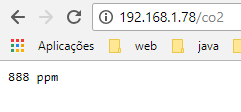
Figure 3 – CO2 measurement returned by the ESP32 server.
If we try the temperature route, we should get an output similar to figure 4. As illustrated, it returns the temperature value appended with the unit, like we defined in the route handling function.
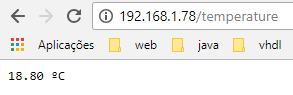
Figure 4 – Temperature measurement returned by the ESP32 server.
Finally, figure 5 illustrates the result for the humidity endpoint. The behavior is similar and, as expected, we get the measurement and its unit.
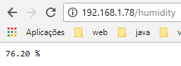
Figure 5 – Humidity measurement returned by the ESP32 server.
Related Product

Recent Blogs

Hands-On Test of 6 New 4K USB Cameras: Resolution, Color, Field of View, and Compatibility
Compare six 4K USB cameras using IMX415, IMX274, and IMX678 sensors across resolution, color, field of view, distortion, Linux, and low-light tests.
REVIEWS Jul 23 2026

Fermion BMI323 6-Axis IMU Engineering Test Notes: Accelerometer, Gyroscope, Step Counter, and I2C Address Verification
This article is an engineering test note, mainly intended to demonstrate the actual performance of the module in common development scenarios, rather than a laboratory calibration report.
REVIEWS Jul 15 2026

Meet DFRobot at FAB26 Boston 2026: AI, Open-Source Hardware & Maker Education
Visit DFRobot at FAB26 Boston for hands-on AI workshops, open-source hardware demos, and practical insights into K–12 maker education.
NEWS Jul 15 2026